Fig. 4.
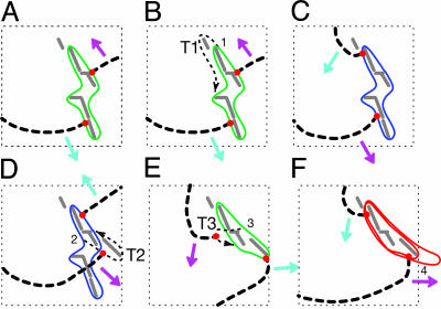
Transitions from P-1 to P-2 and P-2 to P-4 rendered from the changes in orbits of spiral wave tips. (A) P-1 orbit (green line). (B) P-1 orbit (green line) and a transient passage T1. (C) P-2 orbit (blue line). (D) P-2 orbit (blue line) with a transitory passage T2. (E) another P-1 orbit (green line) with a transient passage T3. (F) P-4 orbit (red line). All transient and transitory tip passages (T1, T2, and T3) are marked by black dotted lines, wave fronts are marked by black dashed lines, tip locations are marked by red dots, and the conduction blocks are shown in gray solid lines. The indices 1–3 in B, D, and E mark specific locations where phase slips take place, and the index 4 marks the location of possible 2:1 partial conduction block that splits the orbit into a double-loop.

