

Abstract
We propose a scheme to generate entanglement between microwave fields and achieve strong squeezing of the optical output field in an opto-magnomechanical ring cavity. The system consists of two elastic yttrium iron garnet crystals with attached mirror pads inside two separate microwave cavities, and an extra fixed mirror outside the microwave cavities is utilized to complete the optical ring cavity with the two mirror pads. A magnon mode supported by the yttrium iron garnet crystal couples directly to the microwave cavity mode via magnetic dipole interaction and couples indirectly to the optical cavity mode via magnomechanical displacement, which is caused by magnetostrictive interaction and also couples the magnon mode to a phonon mode. A squeezed light is fed into the ring cavity to entangle the two phonon modes. To activate the beam splitter interaction, each magnon mode and optical cavity mode is driven by a strong red-detuned driving field. Consequently, the stationary entanglement between the two microwave cavities is obtained. The transfer efficiency of the entanglement is  . To ensure the squeezing of the magnon mode generated by magnetostrictive interaction transferred into the optical field, we remove two microwave cavities. The squeezing of the optical output field can reach up to
  dB at 10 mK and survives up to an environmental temperature about 500 mK. Our scheme may find various useful applications in quantum wireless fidelity network and the enhancement of sensitivity of measurements.
Keywords: Opto-magnomechanical system, Quantum entanglement, Squeezing
Subject terms: Quantum optics, Other photonics
Introduction
Quantum entanglement is one of the most important phenomena in quantum mechanics, which plays a significant role in quantum metrology1–3 and quantum sensing4–6. Squeezed states, important quantum states, are significant for improving the sensitivity of many measurements including magnetic resonance spectroscopy7, position measurement8 and biological measurement9. Numerous schemes have been proposed to generate these quantum states based on many platforms or systems, in which the cavity optomechanical (COM) systems10,11 and the cavity magnomechanical (CMM) systems12,13 are hotly investigated platforms.
Cavity optomechanical systems are used to explore the interaction between mechanical motion and microwave cavity photons via radiation pressure14,15. Over the past decade, significant progress has been made in COM systems. Notable examples include entanglement of two harmonic oscillators16,17, quantum squeezing of mechanical motion18,19, ground-state cooling of mechanical oscillators20,21, quantum entanglement and quantum steering22–24, enhanced weak force sensing25, and research of the normal mode splitting26. Similar to COM systems, CMM systems based on yttrium iron garnet (YIG) crystals feature magnetostrictive interactions between the magnon mode and the phonon mode12,13. Compared with COM systems, CMM systems offer better tunability because YIGs possess a high spin density and a low damping rate12,13, which shows promise in diverse potential applications. So far, entanglement of macroscopic objects27–29, bipartite and tripartite entanglement and quantum steering30–36, ground state cooling37, magnomechanically induced transparency, Fano reasonace, slow/fast light38, and generation of squeezed states39,40 have been studied in the CMM systems.
Through the use of YIG micro bridge structures41, the combination of COM systems and CMM systems can be realized by coupling magnomechanical displacement to an optical cavity via radiation pressure42. This forms a new optomagnomechanical (OMM) system, featuring two nonlinear interactions: magnetostrictive and radiation pressure interactions. Current research on OMM systems mainly focuses on the preparation of entangled states between different modes43–48, magnomechanically induced transparency49, Fano-type optical response and the four-wave mixing process50, preparation of magnonic squeezed states51. To the best of our knowledge, there are currently no effective methods generating strong squeezing of the optical output fields in the OMM systems. So in this article we report a new scheme.
In this article, we propose a scheme to generate entanglement between two microwave fields and achieve strong squeezing of the optical output field in an OMM ring cavity. This ring cavity consists of one fixed mirror and two highly reflective mirror pads, each of which is attached to a YIG micro-bridge. Two YIG crystals are embedded in each microwave cavity and subjected to uniform bias magnetic fields. The magnon and phonon modes are supported by the YIG crystals with micro-bridge structures. Microwave driving fields are applied perpendicularly to each micro-bridge to activate the phonon modes. The phonon modes couple to the magnon modes through magnetostrictive interaction and to the optical cavity mode via radiation pressure. At the same time, the magnon modes couple to the microwave cavity modes via magnetic dipole interaction. A squeezed light is fed into the ring cavity through the fixed mirror to couple the two phonon modes. The magnon modes and the optical cavity mode are driven by strong red-detuned microwave fields and an optical field. Therefore, the magnon-phonon-photon beam splitter interaction is activated. Consequently, the two microwave cavity modes are entangled. In the geometric configuration used in the experiment, we determine the optimal parameters for generating maximum entanglement between the two microwave fields. Next, we investigate the effects of different parameters and ambient temperature on the bipartite entanglements and determine how the configuration affects the entanglement between the two microwave cavity modes. The magnetostrictive interaction results in quadrature squeezing of the magnon mode. This squeezed state can be transferred via the beam splitter interaction. To generate stronger squeezing of the optical output field, we remove two microwave cavities. By exploring the parameter space, we identify the optimal parameters for producing maximum squeezing of the optical output field.
The article is organized as follows: In “System and model”, we depict the CMM ring cavity and provide its Hamiltonian. Then we derive Langevin equations of each mode and obtain the Lyapunov equation for the steady-states by applying the linearization method. And we use logarithmic negativity to quantify entanglement. We also derive the optical output field’s noise spectral density (NSD). In “Numerical simulation and results”, we numerically calculate the entanglement and squeezing under different parameter spaces and provide optimal parameters to get strong squeezing of the optical output field. In “Conclusion”, we give a brief conclusion.
System and model
As depicted in Fig. 1a, we devise an OMM ring cavity, which consists of one fixed mirror and two mirror pads. The two mirror pads are attached on the YIG micro bridges41 inside two separate microwave cavities. Additionally,  denotes the angle formed by the incident and reflected light on the mirror pad surfaces. This OMM ring cavity system consists of two phonon modes, two magnon modes, two microwave cavity modes and one optical cavity mode. The magnon modes are embodied by a collective motion of a large number of spins in YIG crystals. They are placed near the maximum magnetic field to establish the interaction between the magnon modes and the microwave cavity modes27. We apply bias magnetic fields and drive magnetic fields to YIG crystals to activate the magnon modes and enhance the magnetomechanical coupling, respectively. The bias magnetic fields, the drive magnetic fields, and the magnetic fields of the microwave cavities are perpendicular to each other where the crystals are placed28. As shown in Fig. 1b,the phonon modes couple to the magnon modes via magnetostrictive interaction12,40 and to the optical cavity mode via radiation pressure10,14. A squeezed light and a laser are fed into the ring cavity through the fixed mirror, with frequencies
  and
and  respectively. The Hamiltonian of this OMM ring cavity system reads
 |
1 |
where the first term contains the annihilation (creation) operators for two microwave cavity modes, two magnon modes, two phonon modes, and one optical cavity mode, denoted by  . They satisfy the commutation relation
  .
.  are the resonance frequencies of the seven modes.
  are the magnetic dipole interaction strength constants.
  are the bare magnonmechanical (optomechanical) coupling strength, which are typically weak and can be effectively enhanced by applying the magnon modes (optical cavity) with strong fields. The signs of the fourth and fifth items are opposite because the radiation pressure forces exerted on the two mirror pads are opposite17. Especially, the fifth term changes from negative to positive when
  16. The last term reads
  , where
  31. It indicates the interaction strength between the magnon mode and the microwave cavity mode.
  is the gyromagnetic ratio.
  denotes the amplitude of the drive magnetic fields.
  represents the total spin number of spins.
  denotes the spin density of YIG crystals and
  corresponds to the volume of the micro bridge structures13.
  denotes the coupling strength of the optical cavity, where
  is the power (free frequency) of the laser field, and
  is the cavity decay rate43.
Fig. 1.
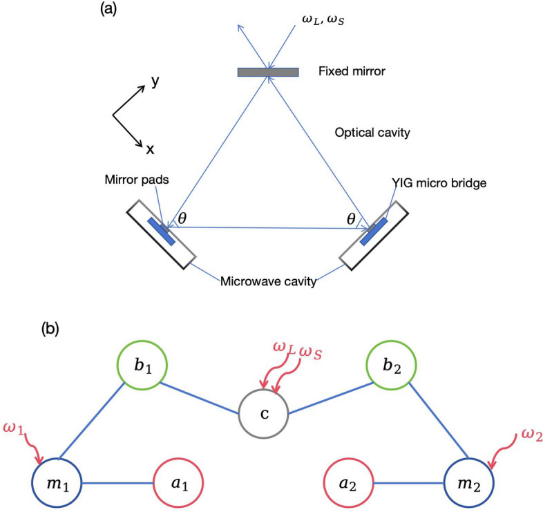
(a) Sketch of the OMM ring cavity. Two mirror pads and one fixed mirror constitute this ring optical cavity. The two mirror pads are attached to the YIG micro bridges, which are embedded in two separate microwave cavities, respectively.  denotes the angle formed by the incident and reflected light on the mirror pad surfaces, which characterize the geometric configuration of the OMM ring cavity. A squeezed light and a laser are fed into the ring cavity through the fixed mirror, with frequencies
  and
and  respectively. (b) Sketch of the interactions in the OMM ring cavity.
  represent two subsystems. The phonon mode (
 ) couples to the magnon mode (
 ) through the magnetostrictive interaction, to the optical cavity mode (c) via radiation pressure. Simultaneously, the magnon mode couples to the microwave cavity mode (
 ) by exploiting the magnetic dipole interaction. The magnon mode with frequency
  is driven by a microwave field with frequency
  to enhance the interaction strength between the magnon mode and the phonon mode. The squeezed light couples the two phonon modes by increasing the number of photons in the cavity and applying greater radiation pressure on each mirror pads.
Working in the interaction picture with respect to  , the quantum Langevin equations (QLEs) of different modes are derived as follows39:
 |
2 |
 |
3 |
 |
4 |
 |
5 |
 |
6 |
where  ,
,  ,
,  . And
. And  are the decay rates of microwave cavities, magnon modes, phonon modes and optical cavity respectively. We choose
  and
and  to activate magnon-phonon-photon beam splitter interaction and cool the mechanical motion, which are the essential conditions to generate entanglement43. We explain the two functions of the input squeezed light as follows. i) As for the generation of entanglement between different modes, it produces a stronger radiation pressure and couples the two phonon modes17. The two microwave cavity modes are entangled via a series of beam splitter interactions. ii) We aim to generate strong squeezing of the optical output field by exploiting the correlation between the amplitude and the phase of the magnon mode, caused by the magnetostrictive interaction52. The squeezing can be transferred to the optical cavity mode by beam splitter interactions, so the squeezing is enhanced twice. This function of enhancing the squeezing degree can be realized through this device.
The correlation functions of the noise operator  are
are  ,
,  ,
,  and
and  , where
  and
and  . r is the squeezing parameter and
  is the squeezing phase of the squeezed vacuum field40. The mean value of other noise operators (
 ) is zero. The correlation functions are
  , and
, and  =
= , where
  is the Boltzmann distribution at thermal equilibrium with temperature T.
Here, we apply strong drive fields onto the magnon and the optical cavity modes, respectively, which lead to  . So we can linearize the system dynamics by substituting
  into the QLEs and neglecting the second-order fluctuation terms19. The steady-states values of each mode are as follows:
 |
7 |
 |
8 |
 |
9 |
 |
10 |
 |
11 |
where  and
and  . The frequency shift terms are induced by mechanical displacements due to magnetostrictive interaction and radiation pressure interaction, respectively. They are typically small and we can assume
  and
and  29. Given that
  , we can neglect the corresponding terms in steady state solutions27. So the steady-states values of the two magnon modes and the optical cavity mode are pure imaginary numbers. Then, we introduce the slowly moving operators in the new reference frame30, where the transformation relation is
  . Here, we set
  .By neglecting fast oscillating non-resonant terms and introducing quadratures of corresponding fluctuations 30, we derive a set of linearized QLEs for the system’s quantum fluctuations, which are expressed in matrix form as
 |
12 |
where  ,
,  and
and 
 Among, we define the quadrature component of operators and their corresponding input noise, e.g.
  and
and  . And the drift matrix A is given as follows.
 |
13 |
where  is the
  zero matrix and
  .
.  , and
, and  are the coupling matrices for the magnon-microwave cavity, magnon-phonon, and optical cavity-phonon subsystems.
  ,
,  .
.  (
( ) are the effective magnomechanical (optomechanical) coupling rates. Here
  and
and  are pure real numbers, because
  and
and  are pure imaginary numbers.
Owing to the linearized dynamics and the Gaussian nature of input noise, the system preserves Gaussian states for all times. The steady-state of system quantum fluctuation is a seven-mode Gaussian state, which can be represented by a 14  14 covariance matrix (CM) defined as
  , where
  . The steady state CM
  can be obtained by solving the Lyapunov equation:
 |
14 |
here the diffusion matrix  is a block diagonal matrix with
 |
15 |
 ,
,  and
and  .
.  ,
,  ,
,  . After the CM of this system is obtained, we can calculate entanglement by extracting the submatrices corresponding to the modes we want to analyze. When entanglement occurs within a composite quantum system, its state cannot be written as the product of the subsystem states. This phenomenon is referred to as quantum entanglement. The preparation of stable and widely applicable entangled states in experiments may potentially be addressed by cavity optomechanics11 and cavity magnetomechanics13. In numerical simulations, we will study the influence of various factors on different bipartite entanglements. We choose the logarithmic negativity to quantify the entanglement of the Gaussian states55. To maintain the flow of the text without diverting from the main discussion, this measure is introduced in the supplementary material.
Furthermore, the Routh-Hurwitz criterion can be used to assess the stability of steady-states, and the Ross table can be utilized to find the stable steady-state parameters52.
Subsequently, we give a brief introduction on how to get strong squeezing of the optical output field. We make use of magnetostriction interactions to generate a quadrature squeezing of the magnon modes52 and exploit beam splitter interaction to transfer it into the optical fields. Our aim is to obtain the strong squeezing of the optical output field, and the interaction between the microwave photon mode and the magnon mode reduces the squeezing degree, so we remove the two microwave cavities. We provide a concise overview of calculating the NSD for the optical output field. In the context of the slowly rotating frame, a set of QLEs is obtained for quantum fluctuations. These equations can be straightforwardly solved by implementing the Fourier transform on each equation. The expression for the quantum fluctuations  can be derived and expressed as29:
 |
16 |
We need to transform the noise correlations in the frequency domain. We report them in the supplementary material. Subsequently, we utilize the standard input-output relation,  54. The phase of the local oscillator is important in the output field due to the use of homodyne detection. Consequentlly, we define the quadrature of the optical output field53:
 |
17 |
with  being the phase. For
  ,
,  , which is the amplitude (phase) fluctuation of the optical output field. The NSD of the quadrature of the optical output field is defined as
 |
18 |
By utilizing the input noise correlations, the spectrum can be obtained. Additionally, when  is less than that of the vacuum state, i.e.
  , the optical output field is squeezed. The corresponding derivations are in the supplementary material.
Numerical simulation and results
In the geometric configuration used in the experiment, we present the entanglements of the two phonon modes  , the two magnon modes
  , the two microwave cavity modes
  and between the optical cavity mode and the phonon mode
  . Then we further investigate the entanglement
  ,
,  ,
,  ,
,  as functions of the cavity-magnon coupling
  and the effective magnomechanical coupling rates. Afterwards we plot the bipartite entanglements versus decay rates. And we investigate the negative effect of temperature on all bipartite entanglements. Subsequently, we consider how the configuration impacts the entanglement
  . Finally, we find the optimal parameters for producing the maximum squeezing of the optical output field and consider the impact of the configuration. In the process of the numerical simulation, the steady state of the system is ensured by the condition that all eigenvalues of the drift matrix have negative real parts according to the Routh-Hurwitz criterion.
Figure 2 shows the stationary entanglements. For simplicity, we assume that the two opto-magnomechanical subsystems are symmetrical. The selection of parameters is within the range of typical values that are practicable in experiments12,43,44:  GHz,
GHz,  GHz,
GHz,  MHz,
MHz,  MHz,
MHz,  MHz,
MHz,  Hz,
Hz,  MHz,
MHz,  MHz,
MHz,  Hz,
Hz,  KHz and
  mK. Compared with the
  mHz magnon-phonon coupling rate for a
 YIG sphere in experiment, we choose a much smaller YIG crystal, which allows the higher magnon-phonon coupling rates12,42. As for the effective magnomechanical coupling rate
  , we choose the order of MHz corresponding to the driving power of
  mW for a
 YIG cuboid42. The order of MHz optomechanical coupling rate is used for cooling. This corresponds the laser power
  mW for
  KHz43. For the geometrical configuration of this device, we choose
  15,17.
Fig. 2.

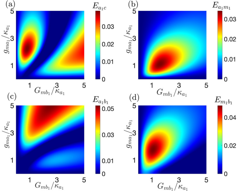
Density plot of stationary entanglement (a)  , (b)
, (b)  , (c)
, (c)  , (d)
, (d)  . Parameters for the squeezed field are
  and
and  . The effective magnomechanical (optomechanical) coupling rates are same. i,e,
  and
and  . And the other parameters are in the main text, which fall within the range of typical values that are practical for experiments.
In Fig. 2a, the phonon modes are gradually activated when  . When
  is fixed, the entanglement
  increases as
  increases. We notice that when
  , the entanglement is 0, which means the beam splitter interaction between the optical cavity mode and the phonon modes is invalid. In Fig. 2b, We can see the entanglement increases when the effective coupling rate increases, because the beam splitter interaction are gradually strengthen when the parameters increase. Fig. 2c shows the entanglement between the two microwave cavities. When
  , the maximum microwave fields entanglement
  is obtained. Then we explain the physical mechanism of transfer efficiency. The input squeezed light shapes the noise properties of quantum fluctuations of the cavity field, exerting stronger radiation pressure on the two movable mirror pads and entangling the two phonon modes. The quantum correlation is transferred from the phonon modes to the magnon modes, then to microwave cavity modes through the optomechanics, magnomechanics, and magnon-microwave beam splitter interactions.The transfer efficiency is
  . Compared with the scheme proposed by K. Di et al.43, our scheme change cavity geometry and use numerical optimization to promote the transfer efficiency. In Fig. 2d, we can see the entanglement between the phonon mode and the optical cavity mode is unexpectedly smaller than the two phonon modes. The reason is we choose large optomechanical coupling rates, which effectively transfer quantum correlations from the optical cavity mode to the phonon modes.
In Fig. 3, we further investigate the entanglement  ,
,  ,
,  ,
,  as functions of cavity-magnon coupling
  and effective magnomechanical coupling rates. Figure 3a shows the entanglement between the microwave cavity mode and the optical cavity mode. There are two regions with large entanglement values. one region is near
  , and the other region is near
  . When
  is held constant, as
  increases,
  initially increases, then gradually decreases, and subsequently increases again. Therefore, we can control the entanglement
  by adjusting the driving power. This is because the effective magnomechanical coupling coefficient is related to the steady-state solution of the magnon mode, which in turn is related to the driving power applied to the YIG crystal. Figure 3b shows the entanglement between the microwave cavity mode and the magnon mode. We notice that when
  , the entanglement is 0. That means the microwave cavity mode and the magnon mode get entangled after introducing the magnon-phonon interaction27. It can be seen that the maximum
  appears at
  Figure 3c shows the entanglement between the microwave cavity mode and the phonon mode. We can see that
  is even larger than
  because the mediation of the YIG crystal27. Figure 3d shows the entanglement between the magnon mode and the phonon mode. With the increase of
  ,
,  doesn’t increase all the time, but increases first and then decreases. From Fig. 3, we conclude that if we want to obtain the maximum entanglement, we should choose the appropriate drive power and cavity-magnon coupling rates. The relationship between entanglement and the parameters is not a monotone function40.
Fig. 3.
Density plot of stationary entanglement (a)  , (b)
, (b)  , (c)
, (c)  , (d)
, (d)  Parameters for the squeezed field are
  and
and  .
.  And the other parameters are the same as those in Fig. 2.
In Fig. 4, we investigate the impact of decay rates on entanglement. Lines of the same color in Fig. 4a,b represent the same bipartite entanglement. To enhance clarity, we have magnified two of the bipartite entanglements by a factor of 10, as indicated in the figure. In Fig. 4a, the bipartite entanglement between the two phonon modes, between the microwave cavity mode and the optical cavity mode, and between the microwave cavity mode and the phonon mode initially increase then decrease as  increases. In contrast, other bipartite entanglements increase monotonically with
  In Fig. 4b, all bipartite entanglements initially increase and then remain constant with the increase of
Fig. 4.

Bipartite entanglements between the different modes versus (a) the decay rate of the microwave cavity 1 and (b) the decay rate of the magnon mode. Here we choose 
 and
and  MHz. The other parameters are the same as those in Fig. 3.
In Fig. 5 We consider the negative effect of temperature on entanglement. All bipartite entanglements decreases as T increases. To make the figure clearer, we enlarge two of the bipartite entanglements by a factor of 10 as in Fig. 4. The entanglement between the microwave cavity and the magnon mode, as well as between the magnon mode and the phonon mode can survive up to  mK. And the entanglement between the two phonon modes and between the phonon mode and the optical cavity mode can survive up to
  mK. The remaining bipartite entanglements can survive up to
  mK.
mK.
Fig. 5.

Bipartite entanglements between the different modes versus T. Here we choose 
 And the other parameters are the same as those in Fig. 3.
In Fig. 6, we consider the impact of configuration, squeezing parameter, and environmental temperature on  . As shown in Fig. 6a,
  first increases and then decreases with the increase of
  . The maximum entanglement is obtained when
  . This result differs from the experiment and may provide guidance for configuration optimization15. Here, we don’t explore the situation of
  because it is far from the optimal angle. Figure 6b shows the variation of entanglement
  versus the squeezing parameter r under different environmental temperatures. The entanglement
  increases as the squeezing parameter r increases and still exists when the environmental temperature reaches
  mK. Compared with Ref.31, our scheme effectively exploit the input squeezed light and strong red-detuned fields to activate beam splitter interactions. Quantum correlation between the two phonon modes are transferred to the two microwave cavity modes. The degree of the entanglement is twice that of the original scheme in Ref.31 and has higher temperature robustness. To the best of our knowledge, the control of entanglement between different modes in COM systems and CMM systems is usually achieved by adjusting the amount of detuning and the coupling strength between different modes11,13. In our proposed scheme, we can control the entanglement between two microwave cavity modes by changing the geometrical configuration of the ring cavity, which provides us with a new method to regulate entanglement.
Fig. 6.

The entanglement  versus (a)
  ; (b) squeezing parameter for different environmental temperatures. We take
  and all other parameters are the same as those in Fig. 2a,b. And
  in (b).
In Fig. 7, we plot squeezing S versus  and
and  for diverse environmental temperatures. Here, we use experimentally feasible parameters46:
  GHz,
GHz,  MHz,
MHz,  MHz,
MHz,  Hz,
Hz,  MHz,
MHz,  MHz,
MHz,  MHz and
  mK. Figure 7a shows that optimal squeezing is achieved at
  At the optimal conditions of
  and
and  , we plot Fig. 7b. It shows the impact of configuration under different temperatures. As
  increases, the squeezing S also increases. The squeezing is robust against bath temperature, remaining
  for the temperature being up to
  mK.
mK.
Fig. 7.

The squeezing of the optical output field versus (a)  ; (b)
; (b)  for diverse environmental temperatures. The geometrical parameter
  in (a).
  in (b). Parameters for the squeezed field are
  (4.34 dB) and
  . See text for other parameters.
Our scheme can generate entanglement of two microwave fields and achieve strong squeezing of the optical output field. In Ref.31, Yu et al proposed a scheme that entangles two microwave fields in a CMM system. The entanglement of two microwave fields can reach up to 0.18 and survive at  mK. Compared with Ref.31, our scheme can generate larger entanglement and shows higher robustness. In Ref.43, Di et al entangled two microwave fields via dual-cavity OMM system with the squeezing parameter of injected field
  . The microwave field entanglement is up to
  and the survive temperature is
  mK. Compared with Ref.43, our scheme changes the geometrical configuration and has a higher transfer efficiency of the entanglement. The transfer efficiency increases from 26.5 to 41%, which increases by 1.5 times. However, our proposed scheme has lower entanglement degree and temperature robustness compared to Ref.43. In Ref.53, Qian et al proposed a scheme that achieves squeezing of a microwave output field by reservoir engineering a CMM system. The maximum squeezing is
  dB, and can survive up to an environmental temperature about 100 mK. Different from Ref.53, we propose the scheme to generate strong squeezing of the optical output field in the OMM cavity. The squeezing of the magnon modes originates from the magnetostrictive interaction and can be transferred to the optical field and the microwave field via beam splitter interaction. To get a larger squeezing degree of the optical output field, we remove the microwave cavities. The squeezing can reach up to
  dB and is robust against bath temperature up to 500 mK. Besides, our scheme shows flexible tunability. To get the optimal conditions of the optical output field, Ref.53 used an analog signal generator, while we can realize the same goal by simply changing the geometrical configuration.
Conclusion
In conclusion, we demonstrated a scheme to generate entanglement between microwave fields and achieve strong squeezing of the optical output field in an OMM ring cavity. The steady-state entanglement between the two microwave cavities can reach up to 0.2 and can survive at an environmental temperature about 220 mk. The optimal configuration generating maximum entanglement is  . By exploring the parameter space, we achieved strong squeezing of the optical output field, reaching up to
  dB. All parameters used in our scheme are feasible in practical experiments. Consequently, it is expected to be implemented in experiment. The high-efficiency entanglement of the two microwave cavities can be applied in quantum wireless fidelity network43. The strong squeezing of the optical output cavity may find various applications in improving the sensitivity of magnetic resonance spectroscopy7, position measurement8 and biological measurement9.
Supplementary Information
Acknowledgements
M. Zhang thanks Junzhong Yang for helpful discussions. J. H. Jia thanks Fan Zhou for helpful discussions. This work was supported by the National Natural Science Foundation of China under Grant No. 11475021 and the National Key Basic Research Program of China under Grant No. 2013CB922000.
Author contributions
J.H. J. wrote the main text, prepared Figs. 1, 3, 4 and 5 and conducted a survey. J.H. prepared Figs. 2, 6 and 7. F.X.Z. and M.Z. reviewed the manuscript. M.Z. supervised the whole process.
Data availability
The datasets generated during the current study are available from the corresponding author on reasonable request.
Declarations
Competing interests
The authors declare no competing interests.
Footnotes
Publisher’s note
Springer Nature remains neutral with regard to jurisdictional claims in published maps and institutional affiliations.
Supplementary Information
The online version contains supplementary material available at 10.1038/s41598-025-94745-0.
References
- 1.Maccone, L. & Riccardi, A. Squeezing metrology: a unified framework. Quantum4, 292 (2020) https://quantum-journal.org/papers/q-2020-07-09-292. [Google Scholar]
- 2.Steinlechner, S. et al. Quantum-dense metrology. Nat. Photonics7(8), 626–630 (2013) https://www.nature.com/articles/nphoton.2013.150. [Google Scholar]
- 3.Ahmadi, M., Bruschi, D. E. & Fuentes, I. Quantum metrology for relativistic quantum fields. Phys. Rev. D89(6), 065028 (2014) https://journals.aps.org/prd/abstract/10.1103/PhysRevD.89.065028. [Google Scholar]
- 4.Lawrie, B. J., Lett, P. D., Marino, A. M. & Pooser, R. C. Quantum Sensing with Squeezed Light. ACS Photonics6(6), 1307–1318 (2019) https://pubs.acs.org/doi/10.1021/acsphotonics.9b00250. [Google Scholar]
- 5.Xu, C. et al. Sensing and tracking enhanced by quantum squeezing. Photon. Res.7(6), A14–A26 (2019) https://opg.optica.org/prj/fulltext.cfm?uri=prj-7-6-A14. [Google Scholar]
- 6.Degen, C. L., Reinhard, F. & Cappellaro, P. Quantum sensing. Rev. Mod. Phys.89(3), 035002 (2017) https://journals.aps.org/rmp/abstract/10.1103/RevModPhys.89.035002. [Google Scholar]
- 7.Caves, C., Thorne, K. S., Drever, R. W. P., Sandberg, V. D. & Zimmermann, M. On the measurement of a weak classical force coupled to a quantum-mechanical oscillator. I. Issues of principle. Rev. Mod. Phys.52(2), 341–392 (1980) https://journals.aps.org/rmp/abstract/10.1103/RevModPhys.52.341. [Google Scholar]
- 8.Bienfait, A. et al. Magnetic Resonance with Squeezed Microwaves. Phys. Rev. X7(4), 041011 (2017) https://journals.aps.org/prx/abstract/10.1103/PhysRevX.7.041011. [Google Scholar]
- 9.Taylor, M. A. et al. Biological measurement beyond the quantum limit. Nat. Photonics.7(3), 229–233. 10.1038/nphoton.2012.346 (2013). [Google Scholar]
- 10.Vitali, D. et al. Optomechanical Entanglement between a Movable Mirror and a Cavity Field. Phys. Rev. Lett.98(3), 030405 (2007) https://journals.aps.org/prl/abstract/10.1103/PhysRevLett.98.030405. [DOI] [PubMed] [Google Scholar]
- 11.Aspelmeyer, M., Kippenberg, T. J. & Marquardt, F. Cavity optomechanics. Rev. Mod. Phys.86(4), 1391 (2014) https://journals.aps.org/rmp/abstract/10.1103/RevModPhys.86.1391. [Google Scholar]
- 12.Zhang, X.-F., Zou, C.-L., Jiang, L. & Tang, H.-X. Cavity magnomechanics. Sci. Adv.2, e1501286 (2016) https://www.science.org/doi/10.1126/sciadv.1501286. [DOI] [PMC free article] [PubMed]
- 13.Zuo, X. et al. Cavity magnomechanics: from classical to quantum. New J. Phys.26(3), 031201 (2024) https://iopscience.iop.org/article/10.1088/1367-2630/ad327c. [Google Scholar]
- 14.Genes, C., Mari, A., Tombesi, P. & Vitali, D. Robust entanglement of a micromechanical resonator with output optical fields. Phys. Rev. A78(3), 032316 (2008) https://journals.aps.org/pra/abstract/10.1103/PhysRevA.78.032316. [Google Scholar]
- 15.Gröblacher, S., Hammerer, K., Vanner, M. & Aspelmeyer, M. Observation of strong coupling between a micromechanical resonator and an optical cavity field. Nature460(7256), 724–727 (2009) https://www.nature.com/articles/nature08171. [DOI] [PubMed] [Google Scholar]
- 16.Wei, J.-N., Wang, T., Zhang, S. & Wang, H. F. Controlling Remote Entanglement and One-Way Steering Via a Squeezed Vacuum Field and an Optical Parametric Amplifier. Adv. Quantum Technol.7(4), 2300374 (2024) https://onlinelibrary.wiley.com/doi/10.1002/qute.202300374. [Google Scholar]
- 17.Huang, S.-M. & Agarwal, G. S. Entangling nanomechanical oscillators in a ring cavity by feeding squeezed light. New J. Phys.11(10), 103044 (2009) https://iopscience.iop.org/article/10.1088/1367-2630/11/10/103044. [Google Scholar]
- 18.Xiong, B. et al. Strong mechanical squeezing in an optomechanical system based on Lyapunov control. Photon. Res.8(2), 151–159 (2020) https://opg.optica.org/prj/fulltext.cfm?uri=prj-8-2-151id=426195. [Google Scholar]
- 19.Zhang, J.-S. & Chen, A.-X. Large mechanical squeezing beyond 3dB of hybrid atom-optomechanical systems in a highly unresolved sideband regime. Opt. Express28(9), 12827–12836 (2020) https://opg.optica.org/oe/fulltext.cfm?uri=oe-28-9-12827id=430170. [DOI] [PubMed] [Google Scholar]
- 20.Zhang, X.-Y., Zhou, Y.-H., Guo, Y.-Q. & Yi, X.-X. Simultaneous cooling of two mechanical oscillators in dissipatively coupled optomechanical systems. Phys. Rev. A100(2), 023807 (2019) https://journals.aps.org/pra/abstract/10.1103/PhysRevA.100.023807. [Google Scholar]
- 21.Wang, D.-Y., Bai, C.-H., Liu, S.-T., Zhang, S. & Wang, H.-F. Optomechanical cooling beyond the quantum backaction limit with frequency modulation. Phys. Rev. A98(2), 023816 (2018) https://journals.aps.org/pra/abstract/10.1103/PhysRevA.98.023816. [Google Scholar]
- 22.Kibret, A. A., Beisie, E. A., Mekonnen, H. D., Darge, T. Y. & Tesfahannes, T. G. Generation of quantum correlations through optical parametric amplification in a hybrid optomechanical system. Eur. Phys. J. Plus139, 705. 10.1140/epjp/s13360-024-05511-6 (2024). [Google Scholar]
- 23.Hidki, A., Peng, J.-X., Singh, S. K., Khalid, M. & Asjad, M. Entanglement and quantum coherence of two YIG spheres in a hybrid Laguerre-Gaussian cavity optomechanics. Sci. Rep.14, 11204. 10.1038/s41598-024-61670-7 (2024). [DOI] [PMC free article] [PubMed] [Google Scholar]
- 24.Singh, S. K., Peng, J.-X., Asjad, M. & Nazaheri, M. Entanglement and coherence in a hybrid Laguerre-Gaussian rotating cavity optomechanical system with two-level atoms. J. Phys. B: At. Mol. Opt. Phys.54, 215502. 10.1088/1361-6455/ac3c92 (2021). [Google Scholar]
- 25.Singh, S. K. et al. Enhanced weak force sensing based on atom-based coherent quantum noise cancellation in a hybrid cavity optomechanical system. Front. Phys.11, 1142452. 10.3389/fphy.2023.1142452 (2023). [Google Scholar]
- 26.Singh, S. K. et al. Normal mode splitting and optical squeezing in a linear and quadratic optomechanical system with optical parametric amplifier. Quantum Inf. Process.22, 198. 10.1007/s11128-023-03947-w (2023). [Google Scholar]
- 27.Li, J., Zhu, S.-Y. & Agarwal, G. S. Magnon-Photon-Phonon Entanglement in Cavity Magnomechanics. Phys. Rev. Lett.121(20), 203601. 10.1103/PhysRevLett.121.203601 (2018). [DOI] [PubMed] [Google Scholar]
- 28.Li, J. & Zhu, S.-Y. Entangling two magnon modes via magnetostrictive interaction. New J. Phys.21(8), 085001 (2019) https://iopscience.iop.org/article/10.1088/1367-2630/ab3508. [Google Scholar]
- 29.Qian, H., Fan, Z.-Y. & Li, J. Entangling mechanical vibrations of two massive ferrimagnets by fully exploiting the nonlinearity of magnetostriction. Quantum Sci. Technol.8(1), 015022 (2023) https://iopscience.iop.org/article/10.1088/2058-9565/acab7b. [Google Scholar]
- 30.Zhao, R.-Q., Jia, J.-H., Wu, L.-X. & Zhang, M. Entanglement and steering in a cross-shaped double-cavity with a magnetic sphere and driven by a squeezed vacuum field. Opt. Quantum Electron.56(6), 947 (2024) https://link.springer.com/article/10.1007/s11082-024-06859-w. [Google Scholar]
- 31.Yu, M., Shen, H. & Li, J. Magnetostrictively Induced Stationary Entanglement between Two Microwave Fields. Phys. Rev. Lett.124(21), 213604 (2020) https://journals.aps.org/prl/abstract/10.1103/PhysRevLett.124.213604. [DOI] [PubMed] [Google Scholar]
- 32.Sohail, A., Ahmed, R., Peng, J.-X., Shahzad, A. & Singh, S. K. Enhanced entanglement via magnon squeezing in a two-cavity magnomechanical system. J. Opt. Soc. Am. B40, 1359–1366. 10.1364/JOSAB.484943 (2023). [Google Scholar]
- 33.Amazioug, M., Teklu, B. & Asjad, M. Enhancement of magnon-photon-phonon entanglement in a cavity magnomechanics with coherent feedback loop. Sci. Rep.13, 3833. 10.1038/s41598-023-30693-x (2023). [DOI] [PMC free article] [PubMed] [Google Scholar]
- 34.Amazioug, M., Singh, S., Teklu, B. & Asjad, M. Feedback Control of Quantum Correlations in a Cavity Magnomechanical System with Magnon Squeezing. Entropy25, 1462. 10.3390/e25101462 (2023). [DOI] [PMC free article] [PubMed] [Google Scholar]
- 35.Chabar, N., Amghar, M’bark & Amazioug, M. Enhanced Gaussian interferometric power, entanglement and Gaussian quantum steering in magnonics system with squeezed light. Phys. Lett. A519, 129712. 10.1016/j.physleta.2024.129712 (2024).
- 36.Sohail, A. et al. Controllable Fano-type optical response and four-wave mixing via magnetoelastic coupling in an opto-magnomechanical system. J. Appl. Phys.133, 154401. 10.1063/5.0133156 (2023). [Google Scholar]
- 37.Asjad, M., Li, J., Zhu, S.-Y. & You, J.-Q. Magnon squeezing enhanced ground-state cooling in cavity magnomechanics. Fundamental Research3(1), 3–7. 10.1016/j.fmre.2022.07.006 (2023). [DOI] [PMC free article] [PubMed] [Google Scholar]
- 38.Amghar, M’bark, Chabar, N. & Amazioug, M. Controlling MMIT, Fano resonance, and slow/fast light in a magnomechanical system with an optical parametric amplifier. J. Opt. Soc. Am. B42, 120–128. 10.1364/JOSAB.535185 (2025).
- 39.Chen, Y.-T., Du, L., Zhang, Y. & Wu, J.-H. Perfect transfer of enhanced entanglement and asymmetric steering in a cavity-magnomechanical system. Phys. Rev. A103(5), 053712 (2021) https://journals.aps.org/pra/abstract/10.1103/PhysRevA.103.053712. [Google Scholar]
- 40.Zhang, W., Wang, T., Han, X., Zhang, S. & Wang, H.-F. Quantum entanglement and one-way steering in a cavity magnomechanical system via a squeezed vacuum field. Opt. Express30(7), 10969–10980 (2022) https://opg.optica.org/oe/fulltext.cfm?uri=oe-30-7-10969id=470541. [DOI] [PubMed] [Google Scholar]
- 41.Heyroth, F. et al. Monocrystalline Freestanding Three-Dimensional Yttrium-Iron-Garnet Magnon Nanoresonators. Phys. Rev. Appl.12(5), 054031 (2019) https://journals.aps.org/prapplied/abstract/10.1103/PhysRevApplied.12.054031. [Google Scholar]
- 42.Fan, Z.-Y., Qiu, L., Gröblacher, S. & Li, J. Microwave-Optics Entanglement Via Cavity Optomagnomechanics. Laser Photonics Rev.17(12), 2200866 (2023) https://onlinelibrary.wiley.com/doi/10.1002/lpor.202200866. [Google Scholar]
- 43.Di, K. et al. High-efficiency entanglement of microwave fields in cavity opto-magnomechanical systems. Opt. Express31(18), 29491–29503 (2023) https://opg.optica.org/oe/fulltext.cfm?uri=oe-31-18-29491id=536640. [DOI] [PubMed] [Google Scholar]
- 44.Fan, Z.-Y., Qian, H. & Li, J. Stationary optomagnonic entanglement and magnon-to-optics quantum state transfer via opto-magnomechanics. Quantum Sci. Technol.8(1), 015014 (2023) https://iopscience.iop.org/article/10.1088/2058-9565/aca3cf. [Google Scholar]
- 45.Tadesse, M., Tesfahannes, T. G., Darge, T. Y., Wodado, M. A. & Mekonnen, H. D. Distant bipartite entanglement generation in a hybrid opto-magnomechanical system. AIP. Adv.14(5), 055201 (2024) https://pubs.aip.org/aip/adv/article/14/5/055201/3287829. [Google Scholar]
- 46.Fan, Z.-Y., Qian, H., Zuo, X. & Li, J. Entangling ferrimagnetic magnons with an atomic ensemble via optomagnomechanics. Phys. Rev. A108(2), 023501 (2023) https://journals.aps.org/pra/abstract/10.1103/PhysRevA.108.023501. [Google Scholar]
- 47.Sohail, A., Ahmed, R., Shahzad, A. & Khan, M. A. Magnon-Phonon-Photon Entanglement via the Magnetoelastic Coupling in a Magnomechanical System. Int. J. Theor. Phys.61, 174. 10.1007/s10773-022-05152-4 (2022). [Google Scholar]
- 48.Yang, Z.-B., Yang, R.-C. & Liu, H.-Y. Generation of optical-photon-and-magnon entanglement in an optomagnonics-mechanical system. Quantum Inf. Process.19, 264. 10.1007/s11128-020-02764-9 (2020). [Google Scholar]
- 49.Amghar, M’bark, Chabar, N., & Amazioug, M. (2024). Tunable phonon-photon coupling induces double magnomechanically induced transparency and enhances slow light in an atom-opto-magnomechanical system. Chin. Phys. B33, 120308 https://iopscience.iop.org/article/10.1088/1674-1056/ad8cbb
- 50.Sohail, A., Peng, J.-X., Hidki, A., Khalid, M. & Singh, S. K. Distant entanglement via photon hopping in a coupled cavity magnomechanical system. Sci. Rep.13, 21840. 10.1038/s41598-023-48825-8 (2023). [DOI] [PMC free article] [PubMed] [Google Scholar]
- 51.Fan, Z.-Y., Zhu, H.-B., Li, H.-T., & Li, J. Magnon squeezing via reservoir-engineered optomagnomechanics. APL Photonics9(10), 100804. 10.1063/5.0228364
- 52.Li, J., Wang, Y.-P., You, J.-Q. & Zhu, S.-Y. Squeezing microwaves by magnetostriction. Natl. Sci. Rev.10(5), 247 (2023) https://academic.oup.com/nsr/article/10/5/nwac247/6795305. [DOI] [PMC free article] [PubMed] [Google Scholar]
- 53.Qian, H., Zuo, X., Fan, Z.-Y., Cheng, J. & Li, J. Strong squeezing of microwave output fields via reservoir-engineered cavity magnomechanics. Phys. Rev. A109(1), 013704 (2024) https://journals.aps.org/pra/abstract/10.1103/PhysRevA.109.013704. [Google Scholar]
- 54.Li, J., Zhu, S.-Y. & Agarwal, G. S. Squeezed states of magnons and phonons in cavity magnomechanics. Phys. Rev. A99(2), 021801 (2019) https://journals.aps.org/pra/abstract/10.1103/PhysRevA.99.021801. [Google Scholar]
- 55.Vidal, G. & Werner, R. F. Computable measure of entanglement. Phys. Rev. A65(3), 032314 (2002) https://journals.aps.org/pra/abstract/10.1103/PhysRevA.65.032314. [Google Scholar]
Associated Data
This section collects any data citations, data availability statements, or supplementary materials included in this article.
Supplementary Materials
Data Availability Statement
The datasets generated during the current study are available from the corresponding author on reasonable request.