

Abstract
Microbial desalination cells (MDCs), as an emerging desalination technology, have attracted increasing attention in recent years due to their ability to simultaneously achieve salt removal and wastewater treatment without the need for external energy input. In this study, the performance of two MDC systems with different cathode types—a biocathode (MDC1#) and a permanganate cathode (MDC2#)—was comparatively evaluated for the treatment of saline wastewater, with a particular focus on voltage output, desalination efficiency, and chemical oxygen demand (COD) removal. Experimental results showed that the average output voltage of MDC2# reached 742.02 mV, which was significantly higher than that of MDC1# (695.6 mV). Its maximum power density was as high as 6.22 W/m3, approximately six times that of MDC1#. Moreover, MDC2# exhibited a higher average chloride removal rate in the desalination chamber (32.34 mg/h), compared to 17.13 mg/h for MDC1#, indicating superior desalination performance. However, in terms of electron recovery, MDC1# achieved a much higher average Coulombic efficiency (28.8 ± 18.7%), nearly three times that of MDC2#, suggesting more efficient electron utilization with the biocathode. Regarding ammonium removal, MDC1# demonstrated a higher initial removal efficiency within the first 96 h (74.3%, with an average rate of 4.17 mg/h), but this declined sharply over time, with the later-stage rate dropping to only 0.32 mg/h (less than 10% of the initial rate). In contrast, MDC2# maintained a relatively stable ammonium removal rate throughout the operation (ranging from 0.58 to 3.27 mg/h, with an average of 1.92 mg/h). In addition, both systems achieved stable COD removal at the anode, with efficiencies consistently above 85%. Overall, the permanganate cathode is more suitable for applications that require high voltage output and efficient desalination, whereas the biocathode shows significant advantages in organic pollutant removal and energy recovery. This study provides a theoretical foundation for the rational selection of cathode types based on the characteristics of saline wastewater, offering valuable guidance for optimizing MDC system performance.
Keywords: Microbial desalination cells (MDC), Bio-cathode, Permanganate cathode, Saline wastewater
Subject terms: Environmental impact, Pollution remediation
Introduction
Saline wastewater is primarily generated from industries such as chemical manufacturing, pharmaceuticals, and dye production. It is characterized by a complex chemical composition and high toxicity, typically containing high concentrations of salts and recalcitrant organic pollutants. If discharged without effective treatment, such wastewater can lead to soil salinization, eutrophication of water bodies, and ecological imbalance1.Moreover, the high chloride concentration (> 8 g/L) in the wastewater can significantly inhibit the metabolic activities of aerobic microorganisms, thereby affecting the stability and efficiency of conventional wastewater treatment systems2. With the rapid economic development and ongoing industrialization in China, the total volume of saline wastewater discharged has been continuously increasing, posing severe challenges to both ecological environments and water resource security. Therefore, developing efficient and sustainable treatment technologies is critical for mitigating the environmental risks associated with saline wastewater.
Currently, the desalination of saline wastewater mainly relies on physicochemical methods such as reverse osmosis (RO) and membrane distillation (MD), whose principles are based on separation and concentration techniques for salt removal. However, these technologies usually suffer from high energy consumption, limited applicability, and operational complexity3,4. For example, treating 1m3 of saline wastewater by RO consumes approximately 3–7 kWh, while multi-stage flash (MSF) desalination may consume as much as 6–8 kWh/m3 and generate roughly 6.7 kg CO₂eq of greenhouse gases5. Furthermore, when dealing with saline wastewater with complex components, the treatment efficiency of these conventional methods is often constrained, making it challenging to achieve economical and effective pollutant removal6.
In contrast, microbial desalination cells (MDC) have gradually become a research focus for saline wastewater treatment due to their advantages of low energy consumption, process flexibility, and multifunctional integration. Unlike traditional microbial fuel cells (MFCs), MDCs introduce an additional desalination chamber between the anode and cathode, forming a three-chamber structure. The working principle of MDCs is based on the metabolic activity of electroactive bacteria attached to the anode electrode. These bacteria oxidize the organic matter in the wastewater to produce electrons and protons; the electrons are then transferred through an external circuit to the cathode, where they react with an electron acceptor, resulting in a stable current output. Simultaneously, the electric field established between the anode and cathode drives the directional migration of ions in the desalination chamber: anions move through an anion exchange membrane into the anode chamber, while cations pass through a cation exchange membrane into the cathode chamber, thus achieving the desalination process. By effectively combining the degradation of organic pollutants with salt removal, MDCs not only enable simultaneous wastewater desalination and pollutant removal but also allow for partial energy recovery, demonstrating broad developmental prospects and excellent application potential7,8.
Since the MDC concept was first proposed, researchers have continually enhanced its performance through reactor design optimization, proper selection of cathode electron acceptors, and the development of efficient, low-cost catalysts. For instance, Chen et al.9 improved desalination efficiency by increasing the number of desalination chambers in a stacked MDC (SMDC); Jacobson et al.10 optimized ion migration pathways in a tubular MDC (UMDC) by employing ion exchange membranes; and Jafary et al.11 enhanced the stability and long-term reliability of quadruple MDCs (QMDCs) using polygonal configurations, such as quadrilateral structures.
Furthermore, as MDC operation involves both anodic oxidation and cathodic reduction reactions, the type of cathode used has a certain influence on MDC performance12.Common abiotic cathode electron acceptors include metal ions with high redox potentials and oxygen. For example, Cao et al.13 developed the first MDC using potassium ferricyanide as the catholyte [Fe(CN)₆3⁻ + e⁻ → Fe(CN)₆4⁻, E° = 0.37 V]. In reactors with a desalination chamber volume of 3 mL and a cross-sectional area of 9 cm2, desalination rates exceeding 90% were achieved when treating saltwater with initial concentrations of 5, 20, and 35 g/L. Under a load of 200 Ω, the maximum output power reached 2 W/m2, demonstrating that the potential difference can effectively drive the desalination process. When using permanganate as a cathode electron acceptor, its significant advantage is its high redox potential. For instance, You et al.14 employed permanganate in a dual-chamber MFC [MnO₄⁻ + 4H⁺ + 3e⁻ → MnO₂ + 2H₂O, E° = 1.70 V] and achieved a maximum power density of 115.60 mW/m2—4.5 and 11.3 times higher than that achieved with potassium ferricyanide (25.62 mW/m2) and oxygen (10.2 mW/m2), respectively. The tubular microbial fuel cell (MFC) uses potassium permanganate as the cathode electron acceptor, achieving a maximum power density of 3986.72 mW/m2. In contrast, in the bio-cathode configuration, an aerobic bio-cathode is employed. Through microbial catalysis, the aerobic bio-cathode enhances electron transfer, improves the electrochemical performance of the system, and may reduce pollutant discharge. To further improve the efficiency of the oxygen reduction reaction (ORR), researchers commonly use precious metals or transition metals as catalysts15. Mehanna et al. 16 employed an air cathode with platinum (0.5 mg/cm2 Pt) as the catalyst, coating four layers of PTFE on 30% moisture-resistant carbon cloth. In a desalination chamber with a volume of 14 mL and a cross-sectional area of 7 cm2, seawater with initial salinities of 5 and 20 g/L achieved desalination rates of 43–67%. To reduce costs and minimize the use of precious metals, researchers have developed more affordable transition metal catalysts. Li et al. 17 used cobalt-copper catalysts (Co-OMS-2, Cu-OMS-2) synthesized from metal-doped octahedral manganese dioxide molecular sieves (OMS-2). When the load resistance was 100Ω, the peak currents were 0.19 mA and 0.2 mA, respectively, demonstrating higher performance than platinum catalysts. Liu et al. 18 prepared the MNOX catalyst via electrodeposition as a replacement for precious metal catalysts, achieving a maximum power density of 772.8 mW/m3. Cheng et al.19 demonstrated that CoTMPP could also serve as a cathode catalyst, replacing platinum. Given the high costs of catalysts during long-term operation, researchers have further developed cost-effective biological cathodes20. Electrochemically active microorganisms, as biocatalysts, not only effectively promote redox reactions and enhance desalination rates but also possess sustainability and self-regeneration abilities21. According to the type of terminal electron acceptor, biological cathodes can be classified as aerobic or anaerobic. Meng et al.22 constructed a BMDC, where the anode pH remained between 6.6 and 7.6 during stable operation. When the initial salinities were 5 g/L and 10 g/L, the desalination rates after 24 h were 46.37 ± 1.14% and 40.74 ± 0.89%, respectively. After 130 days of stable operation, the BMDC achieved a maximum output power of 3.178 W/m3 and an open-circuit voltage (OCV) of 1.118 V. Wen et al.23 constructed an aerobic biological cathode using carbon felt and bacterial catalysts, achieving a peak voltage of 609 mV, which was 136 mV higher than that of an air cathode under the same conditions. When using 441 mL of anode solution to treat seawater with an initial salinity of 35 g/L, the desalination rate reached 92%, with a coulombic efficiency of 96.2 ± 3.8%. In summary, the development of MDCs shows that optimizing reactor structures, selecting appropriate cathode electron acceptors, and developing efficient and low-cost catalysts can effectively improve desalination efficiency and energy recovery.
Based on the above considerations, this study selected representative types of bio-cathodes and abiotic cathodes to compare their performance in treating saline wastewater. In the abiotic cathode configuration, potassium permanganate was chosen as the electron acceptor due to its high redox potential [MnO₄⁻ + 4H⁺ + 3e⁻ → MnO₂ + 2H₂O, E° = 1.70 V; MnO₄⁻ + 2H₂O + 3e⁻ → MnO₂ + 4OH⁻, E° = 0.59 V]. Potassium permanganate can accept electrons and be reduced to manganese dioxide under both acidic and alkaline conditions; as the reaction proceeds, its oxidizing ability gradually diminishes, eventually forming stable MnO₂ precipitates. Experimental observations revealed that, after cyclic operation, the color of the permanganate solution gradually changed from deep purple to brown, indirectly indicating a gradual reduction in its oxidizing capacity. In the bio-cathode configuration, an aerobic bio-cathode was used. The aerobic bio-cathode enhances electron transfer through microbial catalysis, thereby improving the overall electrochemical performance of the system and potentially reducing pollutant discharge. This study investigates the impact of cathode type on the comprehensive performance of MDCs by evaluating output voltage, organic pollutant removal, and desalination efficiency, with the aim of providing a theoretical basis and experimental support for further optimization of MDC systems.
Materials and methods
MDC structural design
The microbial desalination cell (MDC) comprises three chambers: anode, desalination, and cathode (as depicted in Fig. 1). The reactor is constructed from 12 mm thick polymethyl methacrylate (PMMA). When the cathode, desalination, and anode chambers are completely filled with liquid, the volumes of each chamber are 255 mL, 160 mL, and 255 mL, respectively. After adding electrode materials, the effective liquid volumes in the anode and cathode chambers are both reduced to 240 mL. To ensure the system’s sealing and effectively prevent liquid leakage, silicone gaskets are installed between the cathode, anode, and desalination chambers for sealing. Additionally, an anion exchange membrane (AEM, AMI 7001 s, Membranes International) is placed between the anode and desalination chambers, and a cation exchange membrane (CEM, CMI-7000 s, Membranes International) is placed between the desalination and cathode chambers, with both membranes having an effective area of 80 cm2. Before use, the AEM and CEM are soaked in a 2–5% NaCl solution for 24 h to ensure their hydration and stable performance.The ion exchange membranes used in this study were selected based on the application results of MDC-related studies in existing literature16,22–29. Although the internal resistance of these membranes is slightly higher than some high-performance membranes, they possess strong chemical stability, excellent mechanical strength, good resistance to fouling, and a favorable cost-performance ratio. Therefore, they are more suitable for the medium- and long-term continuous operation conditions required for this study. Previous studies have shown that nitric acid pretreatment can significantly improve the electrochemical performance of carbon felt electrodes, doubling the power density of microbial fuel cells (MFCs)30. To optimize the electrode performance, this study adopted the same electrode pretreatment method as Hidalgo et al. 30. The specific steps are as follows: first, the graphite felt electrode is placed in acetone for ultrasonic cleaning for 10 min to remove surface organic contaminants and residual impurities. It is then repeatedly rinsed with ultra-pure water (18.25 MΩ·cm) and dried at room temperature for later use. Next, the dried graphite felt is soaked in 500 mL of 5% (v/v) HNO₃ solution, and stirred at 80 °C for 10 h to further activate the electrode surface and remove deep impurities. After the acid treatment, the electrode is rinsed several times with ultra-pure water (18.25 MΩ·cm) until the pH of the rinse water is close to neutral. Finally, the treated electrode is connected to an external circuit using a platinum electrode clip (JJ110, Beijing Jingke, China). Saturated calomel electrodes (SCE; 0.242 V vs. SHE, Leici, China) are placed in the anode and cathode chambers as reference electrodes, as close as possible to the working electrode, to minimize the potential difference and improve the measurement accuracy.
Fig. 1.

Structural diagrams of reactors MDC1# (a) and MDC2#(b).
Microorganisms and media
The anode and cathode chambers of MDC1#, as well as the anode chamber of MDC2#, were inoculated with sludge obtained from the secondary sedimentation tank of the Southeast Wastewater Treatment Plant in Changchun. Upon collection, the sludge underwent anaerobic incubation for 24 h to enhance the activity of the activated sludge. Post-incubation, the mixed sludge was combined with the anolyte in a 1:1 ratio in Erlenmeyer flasks, with electrode materials added. The flasks were sealed and placed on a magnetic stirrer for acclimation and biofilm attachment. After five days of acclimation, a small sample of the electrode was taken and observed using scanning electron microscopy (SEM). As shown in Fig. 2, microorganisms successfully attached to the electrode surface. The treated electrode, activated sludge, and culture medium were then transferred into the reactor for subsequent experimental investigations.
Fig. 2.

Scanning electron microscopy (SEM) images of the electrode surface before and after biofilm colonization: (a) control (pristine electrode); (b) after microbial colonization.
For the anode and cathode chambers of MDC1# and the anode chamber of MDC2#, the culture medium utilized sodium acetate as the carbon source, with the following composition per liter of deionized water:CH₃COONa: 0.513 g、 KH₂PO₄: 4.4 g、K₂HPO₄·3H₂O: 3.4 g、NH₄Cl: 0.31 g、CaCl₂·2H₂O: 0.01 g、MgCl₂: 0.1 g、Yeast extract: 0.1 g Trace elements solution: 10 mL. The composition of the trace element solution was as follows (per liter of deionized water): 0.024 g NiCl₂·6H₂O, 0.025 g Na₂WO₄·2H₂O, 0.1 g FeSO₄·7H₂O, 0.1 g CaCl₂·2H₂O, 0.1 g CoCl₂·6H₂O, 0.01 g CuSO₄·5H₂O, 0.01 g AlK(SO₄)₂·12H₂O, 0.01 g H₃BO₃, 0.13 g ZnCl₂, and 0.5 g MnSO₄23.
In the MDC2# system employing permanganate as the cathodic electron acceptor, the catholyte consisted of a 0.13 g/L KMnO₄ solution, which was continuously recirculated between the cathode chamber and a brown reagent bottle using a peristaltic pump (BT100-2 J, China). It is important to note that the catholyte was replaced promptly once a significant drop in cathode potential was observed, to maintain stable system performance. The synthetic saline wastewater was prepared with the following composition per liter of deionized water: 1.67 g CH₃COONa, 15.0 g NaCl, 4.4 g KH₂PO₄, 3.4 g K₂HPO₄·3H₂O, 1.49 g NH₄Cl, 0.01 g CaCl₂·2H₂O, and 0.1 g MgCl₂. This configuration yielded a salinity of approximately 25 g/L, with a measured conductivity of 30.16 mS/cm, indicating a highly saline environment. Although trace amounts of Ca2⁺ and Mg2⁺ were present in the system, their low concentrations did not result in any visible scaling or clogging on the surface of the cation exchange membrane during operation. To further prevent membrane fouling and ensure experimental stability, all membranes were thoroughly rinsed with deionized water at the end of each experimental cycle.
MDC initiation and operation
To simplify the startup procedure of microbial desalination cells (MDCs), which typically involves constructing a microbial fuel cell (MFC) prior to conversion into an MDC—a relatively complex process—this study adopted a direct-startup approach. Specifically, acclimated activated sludge was mixed with nutrient solution at a ratio of 1:10 (v/v), and directly introduced into the anode and cathode chambers of MDC1#, as well as the anode chamber of MDC2#. During the startup phase, an external resistance of 1000 Ω was applied, and the output voltage was continuously recorded. A marked decline in voltage was regarded as the end of one complete power generation cycle, at which point the substrate solution was replaced. Notably, high-purity nitrogen gas was sparged into the anode chamber prior to nutrient replacement to remove dissolved oxygen. When the peak voltage and its duration remained stable over three consecutive cycles, the MDCs were considered successfully started up. Subsequently, the systems were operated under batch-mode conditions.
At the end of each cycle, water samples were collected from the desalination chamber for ion analysis. Results from the comparative experiments indicated that the MDC system exhibited significant advantages in chloride (Cl⁻) removal. Experimental data showed that the removal rate dropped dramatically—by approximately 90%—once the Cl⁻ concentration in the saline solution fell below 1000 mg/L. Nevertheless, considering both removal efficiency and economic feasibility, the MDC still demonstrated promising potential for application within this concentration range. Therefore, in this study, a Cl⁻ concentration below 1000 mg/L was set as the termination point of the desalination cycle during batch operation. Additionally, according to the national standard Discharge Standard of Water Pollutant Discharge Standard (GB 31345–2014), the discharge limit for ammonium nitrogen (NH₄⁺) in specific industrial wastewater is 20 mg/L. Thus, a target NH₄⁺ concentration of less than 20 mg/L was also established as a removal criterion. A desalination cycle was considered complete when both the Cl⁻ concentration fell below 1000 mg/L and the NH₄⁺ concentration was less than 20 mg/L, at which point the saline solution in the desalination chamber was replaced to ensure stable operation. All experiments were conducted in a constant-temperature incubator maintained at 25 ± 1 °C.
Analysis and calculation
At the start and end of each power generation cycle, the pH values of the anolyte and catholyte are measured using a portable pH meter (PH/Cond 340i, Germany). The chemical oxygen demand (COD) concentration of the influent and effluent water is determined according to the national standard HJ/T 399–2007 using the rapid digestion spectrophotometric method. The concentrations of Cl⁻, Na⁺, and NH₄⁺ are analyzed using an ion chromatograph (Thermo Fisher, USA) with AS-19 and CS-12A columns. Prior to analysis, all water samples are diluted 50 times and filtered through a 0.45 μm hydrophilic membrane filter. The internal resistance Rint of the MDC is measured using the variable resistor method. During testing, the anolyte and catholyte, as well as the saline wastewater, are replaced, and the external resistance is adjusted in the range of 10,000 to 50 Ω. The system is maintained in a stable operating state for 20–30 min at each resistance value, and the corresponding voltage values are recorded. The maximum power density of the system occurs when the external load resistance Rext equals the internal resistance Rint31. Therefore, by measuring the load resistance that corresponds to the maximum power density, the internal resistance of the reactor can be determined. Throughout the experiment, the external load resistance (Rext, Ω) is set to 1000 Ω using a resistance box (ZX21, Tianshui, China, with an adjustment range of 0.1–9999.9 Ω). The voltage across Rext is recorded every 6 min using a data acquisition card (Smacq, M2001, China), and this voltage is considered the output potential of the cell. The current (I, A) is calculated using the following equation:
 |
1 |
The current density (j, A/m3) and power density (P, W/m3) during the experiment are calculated using the following equations. Here, Va is the volume of the anode chamber (m3):
 |
2 |
 |
3 |
The resistance of the desalination chamber (Rsaline)32 is calculated using the following equation based on the volume of the desalination chamber and the measured conductivity of the saline wastewater, where EC is the saline conductivity (S/m), L is the thickness of the desalination chamber (m), and Am is the cross-sectional area of the desalination chamber (m2):
 |
4 |
When a reference electrode is inserted into the anode and cathode chambers, the cathode potential (Ec) and anode potential (Ea) are measured. The output voltage (Ecell) is calculated using the following equation, where Rmemb (Ω) is the combined resistance of the anion and cation exchange membranes:
 |
5 |
Coulombic efficiency (CE), which measures the electron recovery rate at the anode, was calculated using the following formula:
 |
6 |
I is the current, and t is the time for one power generation cycle.z is the number of electrons transferred per mole of organic matter oxidized (4 mol /mole, based on oxygen). F is Faraday’s constant (96,485 C/mol). CODi is the chemical oxygen demand of the influent. CODo is the chemical oxygen demand of the effluent. Va is the anode volume of the MDC. MO2 is the molar mass of oxygen (32 g/mol).
Results and discussion
Output voltage analysis of the MDC
To effectively compare the performance differences between the bio-cathode and the potassium permanganate cathode in treating saline wastewater, the output voltage between the electrodes of MDC1# and MDC2# was systematically analyzed after completing a full desalination cycle. As shown in Fig. 3a, when the chloride ion (Cl⁻) concentration in the desalination chamber dropped below 1000 mg/L, MDC1# underwent six stable voltage generation cycles, with a total operation time of 529.3 h and an average liquid replacement cycle of 88.2 h. In contrast, MDC2# completed seven voltage generation cycles (Fig. 3b) within a total of 275.0 h, with an average liquid replacement cycle of only 39.3 h, approximately 44.56% of that of MDC1#.
Fig. 3.

Voltage output profiles for different cathode types: (a) MDC1# and (b) MDC2#.
The maximum and minimum electrode potential differences of MDC1# were 744.15 mV and 661 mV, respectively, with an average potential between electrodes of 695.6 mV. For MDC2#, the maximum and minimum electrode potential differences were 828.05 mV and 650.5 mV, respectively, with an average of 742.02 mV. This indicates that the electrode potential difference of MDC2# was consistently higher than that of MDC1# throughout the operation period. Additionally, during each output voltage cycle, the voltage in both systems exhibited a gradual declining trend. This could be attributed to the progressive maturation of electroactive microbial communities at the anode, leading to an accelerated consumption rate of anodic substrates during the reaction, thereby resulting in a voltage drop33.
Current density is an important parameter that reflects the ion migration rate and the intensity of electrochemical reactions. It directly affects the ion transfer process from the desalination chamber to the adjacent chambers, thereby determining the overall desalination efficiency of the MDC system34. As shown in Fig. 4, the current density curves over time reveal significant differences between the two types of cathodes. For the biocathode (MDC1#), the current density is relatively low at the beginning of the desalination process. As the reaction progresses, it gradually increases and eventually stabilizes after a certain period. The fluctuations in current density during this stage may be attributed to the formation of the biofilm and the gradual enhancement of microbial activity. As the biofilm adapts and matures, the current density correspondingly increases. In contrast, the current density of the potassium permanganate cathode (MDC2#) remains consistently high and stable throughout the entire desalination cycle, indicating that this type of cathode possesses strong electrocatalytic properties and high electron transfer efficiency. The ability of the potassium permanganate cathode to maintain a stable current output over long-term operation contributes to the improved desalination efficiency of the system. Fluctuations in current density are closely related to the intensity of electrochemical reactions34,35. The larger variations observed in the biocathode may affect the long-term stability of the system. On the other hand, the potassium permanganate cathode demonstrates superior current stability, suggesting its clear advantage in sustaining continuous current output and enhancing desalination efficiency.
Fig. 4.

Variation of current density over time (a) MDC1# with biocathode; (b) MDC2# with potassium permanganate cathode).
During the operation of MDC1#, a significant drop in cathode potential was observed upon the replenishment of electron acceptors (e.g., oxygen) to compensate for oxygen loss due to aeration (Fig. 5a, points A, B, and C). The potential gradually recovered to its initial level over time. This phenomenon is consistent with findings by Xie et al.36, who reported that, under oxygen-limited conditions, cathodic potential recovery typically exhibits a time lag. The observed decrease in cathode potential may be attributed to fouling and competition from non-electroactive aerobic microorganisms colonizing the cathode surface. Although these microorganisms do not directly participate in electron transfer processes, they consume dissolved oxygen through their own respiratory metabolism, thereby reducing the oxygen availability at the cathode surface for reduction reactions. This competition for oxygen may result in electron accumulation at the cathode surface, leading to a decline in cathodic potential. In addition, as indicated at point D in Fig. 5a, the anodic potential in the MDC1# system dropped rapidly to below –400 mV following substrate replenishment. In contrast, MDC2#, which utilized a high redox potential oxidant (potassium permanganate) as the cathodic electron acceptor, did not exhibit comparable potential fluctuations upon substrate replacement. As shown in Fig. 5b, the potential difference in MDC2# continuously declined during the first 70 h of operation. This behavior may be ascribed to several factors. First, during the initial operation phase, the colonization of exoelectrogenic bacteria on the anode was still limited, resulting in a reduced rate of electron transfer to the permanganate cathode. This in turn constrained the cathodic reaction kinetics and aggravated activation polarization, thereby shifting the cathode potential in a more negative direction. Second, permanganate ions were rapidly reduced on the graphite felt cathode, while their diffusion rate from the bulk solution to the electrode surface remained relatively low. This created local concentration depletion near the electrode surface, inducing concentration polarization that further inhibited cathodic potential rise.
Fig. 5.

Electrode potential profiles during a single cycle: (a) MDC1#; (b) MDC2#.
With continued operation and sufficient permanganate replenishment, both activation and concentration polarization effects were gradually mitigated, and the cathodic reaction became more stable. Once the electron acceptance rate at the cathode reached a dynamic equilibrium with the rate of electron release by anodic microorganisms, the system’s potential fluctuations stabilized. Meanwhile, as the substrate was gradually consumed, the metabolic activity of the electroactive microbial community on the anode declined, reducing the electron generation rate and resulting in a gradual increase in anodic potential. At approximately 70 h into the operation, replacement of both the anodic and cathodic electrolytes in MDC2# (Fig. 5b, points F and E) led to a marked recovery in the overall potential difference of the system. As indicated by points G and H (representing catholyte replenishment), the cathodic potential began to rise steadily. This could be due to the high concentration of permanganate in the fresh catholyte, which alleviated the previous concentration polarization and improved electron acceptance at the cathode. Simultaneously, the replenished substrate stimulated the metabolic activity of the anodic electroactive microorganisms, enhancing electron generation and transfer to the anode electrode. As a result, the anodic potential decreased, further increasing the overall potential difference of the system.
After the output voltage of the MDC systems stabilized, power density and polarization curve tests were conducted, and the results are presented in Fig. 6. During the tests, the electrolyte in the desalination chamber had a pH of 6.85 and a conductivity of 31.5 mS/cm. For MDC2#, the catholyte (permanganate solution) had a concentration of 100 mg/L, conductivity of 329 μS/cm, and a pH of 7.28. The pH values of both the anolyte and catholyte in MDC1# and the anolyte in MDC2# were all 7.3, with a conductivity of 6.45 mS/cm. Under external resistances of 1000 Ω and 200 Ω, the maximum power density of MDC1# was consistently 1.02 W/m3, while that of MDC2# reached 6.22 W/m3, approximately six times higher than that of MDC1#. This result indicates that, compared to a bio-cathode utilizing aerobic microorganisms as the catalyst, employing potassium permanganate as the cathodic electron acceptor can significantly enhance the power output performance of the system. In addition, potassium permanganate possesses a relatively high redox potential, with a standard electrode potential of 1.70 V (vs. SHE) under acidic conditions and 0.59 V (vs. SHE) under alkaline conditions. This higher redox potential facilitates electron migration toward the cathode, thereby improving the overall charge transfer efficiency of the system and enhancing power output performance14. The polarization curve was obtained using a variable external resistance method, in which the external load was gradually adjusted to measure the relationship between current and voltage. The results showed that the open-circuit voltages of MDC1# and MDC2# were 871 mV and 976 mV, respectively. As the external resistance gradually decreased, the current densities of both systems increased accordingly, while the output voltage declined. As shown in Fig. 6, the slope of the polarization curve for MDC1# was significantly steeper than that of MDC2#, corresponding to internal resistances of 855 Ω and 151 Ω, respectively. This indicates that MDC2# exhibits lower resistive losses and superior electron transfer performance. Moreover, the internal resistance of MDC2# was lower than that of the manganese-based MFC developed by You et al.14, further confirming the significant electrochemical advantages of the system.
Fig. 6.

Polarization and power density curves of the microbial desalination cell.
Analysis of solute removal in the desalination chamber
In the initial stage of seawater desalination, the salt concentration in the desalination chamber is significantly higher than that in the anode and cathode chambers. Under the combined influence of the electric field and concentration gradient, the desalination efficiency is significantly enhanced. Specifically, the electric field drives the cations (Na⁺) in the desalination chamber toward the cathode chamber and the anions (Cl⁻) toward the anode chamber. Meanwhile, the concentration gradient between the desalination chamber and the anode/cathode chambers further promotes the diffusion of ions from the high-concentration region (desalination chamber) to the low-concentration regions (anode and cathode chambers). The synergistic effect of these two driving forces accelerates the migration and removal of salts from the desalination chamber, thereby achieving high initial desalination efficiency. As shown in Fig. 7, the removal rate of NH₄⁺ exhibits a steadily increasing trend throughout the entire desalination cycle, reaching a maximum of over 97%, with the overall removal efficiency of MDC1# surpassing that of MDC2#. Detailed analysis reveals that the NH₄⁺ removal rate in the MDC1# system follows a "fast-then-slow" pattern, while that of the MDC2# system remains relatively stable. During the first 96 h of operation, the NH₄⁺ concentration in MDC1# rapidly decreased from 538.6 mg/L to 138.56 mg/L, achieving a removal rate of 4.17 mg/h, indicating high removal efficiency. However, after 96 h, the NH₄⁺ removal rate in MDC1# declined significantly to only 0.32 mg/h, less than 10% of the rate observed in the initial period, suggesting a gradual reduction in removal capacity over long-term operation. In contrast, the NH₄⁺ removal rate in the MDC2# system remained relatively stable throughout the entire experiment, ranging from 0.58 to 3.27 mg/h, with an average rate of 1.92 mg/h, indicating its capability to maintain good performance under prolonged operation.
Fig. 7.
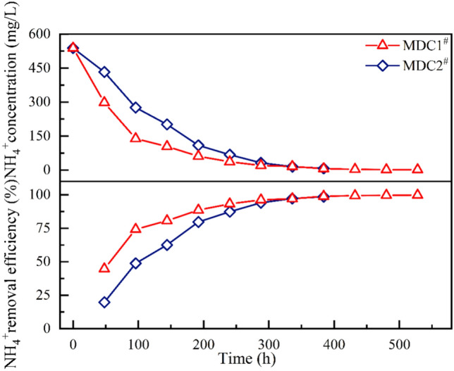
Degradation curve and removal efficiency of NH₄⁺ in the desalination chamber.
Overall, if a short-term high-efficiency removal of NH₄⁺ is required, the MDC1# system demonstrates superior performance and is more suitable for rapid treatment applications. Conversely, for applications that require long-term and stable operation, the MDC2# system offers more consistent removal efficiency. Therefore, in practical engineering applications, the selection of cathode type should be based on specific treatment needs: aerobic biocathodes are preferable for short-term, high-efficiency NH₄⁺ removal, whereas permanganate cathodes are more appropriate for systems that demand long-term operational stability.
As shown in Fig. 8, the Cl⁻ removal rate gradually increased over time, exhibiting a trend similar to that of NH₄⁺, and eventually reached a peak value of approximately 90% in the later stage of the experiment. However, significant differences were observed in the Cl⁻ removal performance between the two cathode types. Specifically, the average Cl⁻ removal rate of MDC2# was 32.34 mg/h, which was substantially higher than that of MDC1# (17.13 mg/h), indicating that the permanganate cathode system had a stronger driving force for ion migration and removal throughout the operational period. Further analysis revealed that the Cl⁻ removal rate in MDC2# exhibited a "fast-then-slow" trend, with a notable inflection point at 144 h. At this stage, the removal rate dropped sharply from the initial peak of 53.17 mg/h to 9.63 mg/h, accounting for only 12.47% of its peak value. This suggests that the removal capacity of MDC2# declined to a certain extent during prolonged operation. In contrast, the Cl⁻ removal rate in MDC1# remained relatively stable, fluctuating around 15 mg/h throughout the experiment, demonstrating better performance stability during long-term operation. In summary, MDC2# exhibited higher Cl⁻ removal efficiency during the initial stage, making it more suitable for short-term intensive desalination applications, while MDC1# showed better long-term stability, making it preferable for continuous desalination scenarios. When considering the removal of NH₄⁺, MDC1# demonstrated superior short-term efficiency, whereas MDC2# showed more stable NH₄⁺ removal performance. Therefore, the cathode type should be selected based on the characteristics of the target pollutants and the expected operational duration to optimize the overall system performance. It is noteworthy that when the salt concentration in the desalination chamber becomes lower than that in the anode and cathode chambers, reverse diffusion may occur—where ions migrate from the low-concentration zones (anode/cathode chambers) back into the high-concentration desalination chamber—thereby reducing the overall salt removal rate and desalination efficiency. This phenomenon is particularly pronounced in MDC systems operating under low current density conditions, which typically arise when using high external resistances (e.g., 1000 Ω) or suboptimal cathode materials with limited electrocatalytic performance that hinder the generation of high current densities37.
Fig. 8.

Variation of Cl⁻ concentration and removal efficiency in the desalination chaber.
COD removal performance analysis
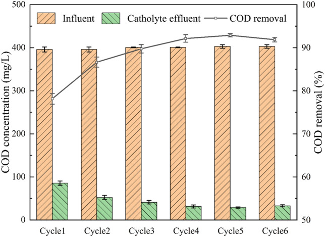
As shown in Fig. 9, there are significant differences in Coulombic efficiency (CE) among the MDC systems with different cathode types. Specifically, the CE of MDC1# was 28.8 ± 18.7%, which was significantly higher than that of MDC2# (9.8 ± 4.4%), approximately three times higher. This indicates that the bio-cathode system has a superior advantage in electron utilization. Further analysis revealed that certain bacteria can connect to each other or to electrodes via specialized structures such as cytochromes and nanowires, enabling efficient electron transfer to specific ions or compounds and thus promoting the desalination process. This stable structure optimizes the electron transfer mechanism, reducing potential electron losses38, thereby enhancing the overall electron utilization efficiency of the system. In contrast, potassium permanganate, as a strong oxidant, undergoes a relatively straightforward reduction reaction at the cathode, without involving complex biological metabolism or electron transport mechanisms. However, during this process, potassium permanganate may still undergo some undesirable side reactions with various substances, resulting in partial loss39. Therefore, although the permanganate cathode operates through a relatively straightforward reaction pathway, its electron utilization efficiency is lower compared to that of the biocathode system. Throughout the entire desalination cycle, the COD removal performance of the MDC1# cathode, MDC1# anode, and MDC2# anode was thoroughly monitored. The results show that COD removal efficiency increased progressively over time, but significant differences were observed among different electrode systems, with the order of performance being: MDC1# cathode > MDC2# anode > MDC1# anode (Fig. 9). Specifically, the COD removal efficiency of the MDC1# anode fluctuated between 35.93 ± 0.77% and 88.12 ± 0.73%, gradually stabilizing after the fourth power generation cycle, with a final average removal efficiency of 85.30 ± 0.81%. In comparison, the MDC2# anode showed less fluctuation, ranging from 47.13 ± 2.61% to 90.40 ± 1.36%, and remained stable at approximately 87.82 ± 1.33% after the fourth cycle. These results indicate that both anode systems exhibited high COD removal capacities and could achieve stable organic matter removal after a certain period of operation.
Fig. 9.

COD degradation performance and removal efficiency curves of the anode and cathode during multiple power generation cycles (a): MDC1# anode, (b): MDC2# anode).
Compared with the anode systems, the MDC1# cathode exhibited a more stable and efficient performance in COD removal (Fig. 10). Specifically, the COD removal efficiency of the MDC1# cathode consistently remained between 78.13 ± 1.25% and 92.87 ± 0.37%, stabilizing after the third power generation cycle and maintaining a high level throughout long-term operation. This performance is likely attributed to the application of aerobic biotechnologies at the cathode. In the MDC1# cathode system, aeration was employed to increase the dissolved oxygen concentration in the solution, which significantly promoted microbial proliferation and metabolic activity. As a result, the microbial degradation capacity was greatly enhanced, providing strong support for efficient COD removal. Based on this mechanism, the MDC1# cathode system was able to maintain high COD removal rates throughout the entire desalination cycle and demonstrated excellent performance even in the initial stages of operation.
Fig. 10.
COD degradation and removal efficiency of MDC1# cathode over multiple power generation.
Changes in anode and cathode pH under varying cathode types
During the entire desalination cycle, the pH values of influent and effluent in both the anode and cathode chambers of MDC1# and MDC2# were monitored (Fig. 11). A phosphate buffer system composed of monopotassium phosphate (KH₂PO₄) and dipotassium phosphate (K₂HPO₄) was added to the anolyte and catholyte of MDC1# as well as to the anolyte of MDC2# to maintain pH stability and mitigate drastic acidification or alkalization. Despite the buffering effect, variations in pH were still observed, particularly in the cathode chambers40–42. In MDC1#, the anode influent and effluent pH decreased from 7.04 ± 0.21 to 6.62 ± 0.36, while the cathode effluent pH slightly increased to 7.36 ± 0.08. A similar trend was observed in the anode chamber of MDC2#, where the influent pH was 7.04 ± 0.21 and the effluent pH decreased to 6.75 ± 0.15. However, a more pronounced pH increase was detected in the cathode chamber of MDC2#, where the influent pH of 6.65 ± 0.12 rose sharply to 9.88 ± 0.70. This significant pH elevation is attributed to the electrochemical reduction of permanganate (MnO₄⁻), which served as the cathodic electron acceptor. According to the electrode reaction mechanism, MnO₄⁻ undergoes the following reaction at the cathode surface: MnO₄⁻ + 2H₂O + 3e⁻ → MnO₂ + 4OH⁻ (E⁰ = 0.59 V). The generation of hydroxide ions (OH⁻) during this process led to an alkaline shift in catholyte pH. This change provides direct evidence of MnO₄⁻ reduction, and the resulting MnO₂ exhibits excellent electrocatalytic properties, enhancing electron transfer and improving both desalination and power generation performance of the system43.
Fig. 11.

pH variations of influent and effluent in anode and cathode chambers under different electrode configurations.
Conclusion
This study demonstrates that the cathode type has a certain influence on the electrochemical behavior and pollutant removal performance of microbial desalination cells (MDCs) treating saline wastewater. The permanganate cathode, due to its high redox potential (E⁰ = 1.7 V in acidic and 0.59 V in alkaline conditions), exhibited higher voltage output and faster chloride ion removal. However, its Coulombic efficiency was relatively low, possibly due to side reactions and electron loss during oxidation. Although permanganate is not the most eco-friendly oxidant, the concentration used in this study was low (100 mg/L), and the final precipitate was identified as manganese dioxide (MnO₂), which helps mitigate environmental risks. In contrast, the aerobic biocathode system showed more efficient and stable performance in organic pollutant removal, along with a significantly higher Coulombic efficiency, indicating greater potential for energy recovery and long-term operational sustainability. Differences in pH variation between the cathode chambers of the two systems further reflected the impact of cathodic reactions on ion migration, providing insight into internal mass transfer and performance regulation. Therefore, cathode type should be selected based on specific treatment objectives. Permanganate cathodes are suitable when high desalination efficiency and voltage output are desired, whereas biocathodes are preferable for ammonium removal, COD degradation, and improved electron utilization.
However, several important aspects need to be addressed in future studies:
Long-Term Performance Assessment: The study mainly focuses on short-term performance. Long-term stability, operational sustainability, and cost-effectiveness need to be evaluated, as these factors are crucial for practical application and system optimization.
Real Industrial Wastewater Testing: The experiments were conducted using synthetic saline wastewater. Testing with real industrial wastewater is essential, as its composition may vary and introduce additional challenges, such as complex organic pollutants or varying ionic strengths, that could impact system performance.
Economic and Environmental Considerations: While the permanganate cathode demonstrated promising performance, the economic feasibility and potential environmental impact of its use need further investigation. In particular, reagent consumption, secondary pollution, and disposal of waste products (e.g., manganese dioxide) may pose operational challenges. A more comprehensive cost–benefit analysis and environmental impact assessment are necessary to evaluate the practicality of permanganate-based systems in large-scale applications.
Future research should focus on multifunctional cathode materials, environmentally friendly alternatives to permanganate, and validation under real saline wastewater conditions. Additionally, the potential transfer of organic compounds—such as acetate—from the saline chamber to the anodic chamber was not assessed in this study and should be carefully monitored in future experiments, as it may affect COD removal interpretation and system efficiency over time.
Acknowledgements
The work was financially supported by the National Natural Science Foundation of China (52470077).
Author contributions
All authors were involved in the conception and design of the study. Hongsheng Jia,Guang Li, Xiaoteng Liu, Xiaoning Ma lianhong Li and Xinrui Han were responsible for material preparation, data collection, and analysis. Hongsheng Jia took the lead in drafting the manuscript, while all authors provided critical comments on previous versions. Guang Li, Xiaoteng Liu Xiaoning Ma lianhong Li and Xinrui Han offered editorial suggestions. All authors read and approved the final version of the manuscript.
Funding
The work was financially supported by the National Natural Science Foundation of China (52470077).
Data availability
The datasets used and/or analyzed during the current study are available from the correspondingauthor on reasonable request.
Declarations
Competing interests
The authors declare no competing interests.
Footnotes
Publisher’s Note
Springer Nature remains neutral with regard to jurisdictional claims in published maps and institutional affiliations.
Publisher’s note
Springer Nature remains neutral with regard to jurisdictional claims in published maps and institutional affiliations.
References
- 1.Lefebvre, O. & Moletta, R. Treatment of organic pollution in industrial saline wastewater: a literature review. Water Res.40, 3671–3682 (2006). [DOI] [PubMed] [Google Scholar]
- 2.Ludzack, F. J. & Noran, D. K. Tolerance of high salinities by conventional wastewater treatment processes. J. Water Pollut. Control. Fed.37, 1404–1416 (1965). [PubMed] [Google Scholar]
- 3.Greenlee, L. F., Lawler, D. F., Freeman, B. D., Marrot, B. & Moulin, P. Reverse osmosis desalination: Water sources, technology, and today’s challenges. Water Res.43, 2317–2348 (2009). [DOI] [PubMed] [Google Scholar]
- 4.Membrane operations : Innovative separations and transformations | semantic scholar. https://www.semanticscholar.org/paper/Membrane-operations-%3A-innovative-separations-and-Drioli-Giorno/ed2ea41d89d35e9a7ec76ec8a60ffebe13705aad.
- 5.Rahman, S., Al-Mamun, A., Jafary, T., Alhimali, H. & Baawain, M. S. Effect of internal and external resistances on desalination in microbial desalination cell. Water Sci. Technol.83, 2389–2403 (2021). [DOI] [PubMed] [Google Scholar]
- 6.Cath, T. Y., Childress, A. E. & Elimelech, M. Forward osmosis: Principles, applications, and recent developments. J. Membr. Sci.281, 70–87 (2006). [Google Scholar]
- 7.Microbial Fuel Cells—Challenges and Applications. Environmental Science & Technology. https://pubs.acs.org/doi/10.1021/es0627592. [PubMed]
- 8.Using microbial desalination cells to reduce water salinity prior to reverse osmosis - Energy & Environmental Science (RSC Publishing). https://pubs.rsc.org/en/content/articlelanding/2010/ee/c002307h.
- 9.Chen, X. et al. Stacked microbial desalination cells to enhance water desalination efficiency. Environ. Sci. Technol.45, 2465–2470 (2011). [DOI] [PubMed] [Google Scholar]
- 10.Jacobson, K. S., Drew, D. M. & He, Z. Efficient salt removal in a continuously operated upflow microbial desalination cell with an air cathode. Biores. Technol.102, 376–380 (2011). [DOI] [PubMed] [Google Scholar]
- 11.Jafary, T. et al. Enhanced power generation and desalination rate in a novel quadruple microbial desalination cell with a single desalination chamber. Renew. Sustain. Energy Rev.127, 109855 (2020). [Google Scholar]
- 12.Freguia, S., Rabaey, K., Yuan, Z. & Keller, J. Sequential anode–cathode configuration improves cathodic oxygen reduction and effluent quality of microbial fuel cells. Water Res.42, 1387–1396 (2008). [DOI] [PubMed] [Google Scholar]
- 13.Cao, X. et al. A new method for water desalination using microbial desalination cells. Environ. Sci. Technol.43, 7148–7152 (2009). [DOI] [PubMed] [Google Scholar]
- 14.You, S., Zhao, Q., Zhang, J., Jiang, J. & Zhao, S. A microbial fuel cell using permanganate as the cathodic electron acceptor. J. Power Sources162, 1409–1415 (2006). [Google Scholar]
- 15.Ge, X. et al. Oxygen Reduction in Alkaline Media: From Mechanisms to Recent Advances of Catalysts. ACS Catal.5, 4643–4667 (2015). [Google Scholar]
- 16.Mehanna, M. et al. Using microbial desalination cells to reduce water salinity prior to reverse osmosis. Energy Environ. Sci.3, 1114 (2010). [Google Scholar]
- 17.Li, X., Hu, B., Suib, S., Lei, Y. & Li, B. Electricity generation in continuous flow microbial fuel cells (MFCs) with manganese dioxide (MnO2) cathodes. Biochem. Eng. J.54, 10–15 (2011). [Google Scholar]
- 18.Liu, X.-W. et al. Nano-structured manganese oxide as a cathodic catalyst for enhanced oxygen reduction in a microbial fuel cell fed with a synthetic wastewater. Water Res.44, 5298–5305 (2010). [DOI] [PubMed] [Google Scholar]
- 19.Cheng, S., Liu, H. & Logan, B. E. Power densities using different cathode catalysts (pt and CoTMPP) and polymer binders (nafion and PTFE) in single chamber microbial fuel cells. Environ. Sci. Technol.40, 364–369 (2006). [PubMed] [Google Scholar]
- 20.Croese, E., Pereira, M. A., Euverink, G.-J.W., Stams, A. J. M. & Geelhoed, J. S. Analysis of the microbial community of the biocathode of a hydrogen-producing microbial electrolysis cell. Appl. Microbiol. Biotechnol.92, 1083–1093 (2011). [DOI] [PMC free article] [PubMed] [Google Scholar]
- 21.Mehanna, M., Kiely, P. D., Call, D. F. & Logan, B. E. Microbial electrodialysis cell for simultaneous water desalination and hydrogen gas production. Environ. Sci. Technol.44, 9578–9583 (2010). [DOI] [PubMed] [Google Scholar]
- 22.Meng, F. et al. Bioelectrochemical desalination and electricity generation in microbial desalination cell with dewatered sludge as fuel. Biores. Technol.157, 120–126 (2014). [DOI] [PubMed] [Google Scholar]
- 23.Wen, Q. Using bacterial catalyst in the cathode of microbial desalination cell to improve wastewater treatment and desalination. Biores. Technol.125, 108–113 (2012). [DOI] [PubMed] [Google Scholar]
- 24.Kokabian, B., Ghimire, U. & Gude, V. G. Water deionization with renewable energy production in microalgae - microbial desalination process. Renewable Energy122, 354–361 (2018). [Google Scholar]
- 25.Zhang, B. & He, Z. Integrated salinity reduction and water recovery in an osmotic microbial desalination cell. RSC Adv.2, 3265 (2012). [Google Scholar]
- 26.Morel, A. et al. Microbial desalination cells packed with ion-exchange resin to enhance water desalination rate. Biores. Technol.118, 43–48 (2012). [DOI] [PubMed] [Google Scholar]
- 27.Hemalatha, M., Shanthi Sravan, J. & Venkata Mohan, S. Self-induced bioelectro-potential influence on sulfate removal and desalination in microbial fuel cell. Biores. Technol.309, 123326 (2020). [DOI] [PubMed] [Google Scholar]
- 28.Goren, A. Y. & Okten, H. E. Energy production from treatment of industrial wastewater and boron removal in aqueous solutions using microbial desalination cell. Chemosphere285, 131370 (2021). [DOI] [PubMed] [Google Scholar]
- 29.Han, X. et al. Remediation of saline-sodic soil by plant microbial desalination cell. Chemosphere277, 130275 (2021). [DOI] [PubMed] [Google Scholar]
- 30.Hidalgo, D. et al. Surface modification of commercial carbon felt used as anode for microbial fuel cells. Energy99, 193–201 (2016). [Google Scholar]
- 31.Logan, B., Cheng, S., Watson, V. & Estadt, G. Graphite fiber brush anodes for increased power production in air-cathode microbial fuel cells. Environ Sci Technol41, 3341–3346 (2007). [DOI] [PubMed] [Google Scholar]
- 32.Ortiz, J. M. et al. Brackish water desalination by electrodialysis: Batch recirculation operation modeling. J. Membr. Sci.252, 65–75 (2005). [Google Scholar]
- 33.Forrestal, C., Xu, P., Jenkins, P. E. & Ren, Z. Microbial desalination cell with capacitive adsorption for ion migration control. Biores. Technol.120, 332–336 (2012). [DOI] [PubMed] [Google Scholar]
- 34.Nandy, A. et al. Influence of carbon-based cathodes on biofilm composition and electrochemical performance in soil microbial fuel cells. Environ. Sci. Ecotechnol.16, 100276 (2023). [DOI] [PMC free article] [PubMed] [Google Scholar]
- 35.Imoro, A. Z., Mensah, M. & Buamah, R. Developments in the microbial desalination cell technology: A review. Water-Energy Nexus4, 76–87 (2021). [Google Scholar]
- 36.Xie, Fei. Study on the characteristics of biocathode microbial desalination fuel cell for pickled mustard wastewater treatment (Chongqing University, 2020).
- 37.Ramírez-Moreno, M. et al. Comparative performance of microbial desalination cells using air diffusion and liquid cathode reactions Study of the salt removal and desalination efficiency. Front Energy Res.10.3389/fenrg.2019.00135 (2019). [Google Scholar]
- 38.He, Z. & Angenent, L. T. Application of bacterial biocathodes in microbial fuel cells. Electroanalysis18, 2009–2015 (2006). [Google Scholar]
- 39.Rhoads, A., Beyenal, H. & Lewandowski, Z. Microbial fuel cell using anaerobic respiration as an anodic reaction and biomineralized manganese as a cathodic reactant. Environ. Sci. Technol.39, 4666–4671 (2005). [DOI] [PubMed] [Google Scholar]
- 40.Zhao, N. Enhanced removal and recovery of ammonium from wastewater using bioelectrochemical systems (BES) (Jiangnan University, 2019).
- 41.Wang, Yongqi. Optimization study on salt removal from pickled mustard wastewater using microbial desalination cells (MDCs) (Chongqing University, 2019).
- 42.Liu, Zhe. Study on the performance of microbial desalination fuel cell (MDC) for pickled mustard wastewater treatment (Chongqing University, 2020).
- 43.Elawwad, A., Ragab, M., Hamdy, A. & Husein, D. Z. Enhancing the performance of microbial desalination cells using δMnO2/graphene nanocomposite as a cathode catalyst. J. Water Reuse Desalination10, 214–226 (2020). [Google Scholar]
Associated Data
This section collects any data citations, data availability statements, or supplementary materials included in this article.
Data Availability Statement
The datasets used and/or analyzed during the current study are available from the correspondingauthor on reasonable request.