

Summary
The urgency to reduce hydrofluorocarbon (HFC) emissions, particularly HFC-125 (pentafluoroethane, CF3CF2H), has driven efforts to develop sustainable alternatives. Herein, we present a method for converting HFC-125 into tetrafluoroethylene (TFE), an industrially valuable monomer for fluoropolymer production. Our approach uses potassium hexamethyldisilazide (KHMDS), optimizing reaction conditions at −50°C to achieve high TFE yields without any observable byproducts. This low-temperature method offers a safer and more sustainable alternative to traditional high-temperature processes for TFE production, which involve hazardous byproducts and complex handling. We also demonstrated that various chemical reactions using freshly generated TFE, including thiol addition, trifluorovinylation, radical addition, amination, alcohol addition, and polymerization, can be performed, extending the utility of this approach. Moreover, a continuous flow process for the conversion of HFC-125 to TFE at room temperature was achieved without cryogenic equipment. This dual-purpose solution addresses both environmental sustainability of fluorochemicals and the growing demand for fluoropolymers in various industries.
Subject areas: Chemistry, Green chemistry
Graphical abstract

Highlights
-
•
Selective dehydrofluorination based on negative hyperconjugation
-
•
Synthesis of tetrafluoroethylene from the pentafluoroethane
-
•
Continuous flow tetrafluoroethylene synthesis at room temperature
-
•
Potassium cation promotes β-fluorine elimination
Chemistry; Green chemistry
Introduction
The quest to replace chlorofluorocarbons (CFCs) and hydrochlorofluorocarbons (HCFCs) has led to the development and widespread use of hydrofluorocarbons (HFCs), which were initially hailed as safer alternatives because of their negligible ozone depletion potential (ODP). Among these, HFC-125 (pentafluoroethane, CF3CF2H) has become prominent in applications such as fire extinguishing agents and refrigerant blends like HFC-410A.1,2,3,4 However, the early optimism surrounding HFCs has been tempered by their high global warming potential (GWP), with HFC-125 having a GWP of 3,450.5 The 2016 Kigali Amendment to the Montreal Protocol was pivotal, marking the recognition of the climate impact posed by HFCs and mandating their phase-down.6,7,8,9,10 In response to these regulatory strides, the urgency to develop more effective and scalable methods for the decomposition of HFC has never been greater, not only just as a matter of environmental stewardship but also as a necessity for mitigating future climate impacts.
An ideal approach to address this challenge involves the transformation of HFC-125 into tetrafluoroethylene (TFE, CF2 = CF2), a key monomer in the production of fluoropolymers, such as polytetrafluoroethylene (PTFE), ethylene tetrafluoroethylene (ETFE), and fluorinated ethylene propylene (FEP) (Figure 1A). TFE is particularly valued for its negligible GWP and ODP,11 making it an environmentally favorable compound in the chemical industry. Traditionally, TFE has been produced by the dimerization of difluorocarbenes (CF2) generated by the pyrolysis of chlorodifluoromethane (R-22) (Figure 1B).12,13,14,15,16,17,18,19 This method, while industrially effective, generates hazardous byproducts, such as hydrogen chloride (HCl) and perfluoroisobutene,20,21,22,23,24 necessitating complex purification and making it less viable for smaller-scale applications. Other industrial methods, such as plasma,25,26 microwave,25 and pyrolysis (at 600–1,000 K)27 degradation of perfluoroalkenes to TFE, have been found to be inefficient. Several laboratory methods have been used for the synthesis of TFE (Figure 1C), such as the dechlorination of 1,2-dichloro-1,1,2,2-tetrafluoroethylene using zinc,28,29,30 pyrolysis of pentafluoropropionic acid salts,31,32 decomposition of PTFE,33,34,35,36,37,38,39,40 or others.41,42,43,44,45,46,47 Recently, Hu et al. reported the synthesis of TFE from the Ruppert-Prakash reagent (Me3SiCF3) in the presence of sodium iodide through the generation of CF2.48 However, these synthetic approaches are not viable on an industrial scale. As the global fluoropolymer market is projected to grow at a compound annual growth rate (CAGR) of approximately 6% between 2023 and 2033,49 driven by demand from the automotive, electronics, and renewable energy sectors, the need for more sustainable and scalable production of TFE is evident.50,51,52,53,54 This demand, coupled with the environmental imperative for managing HFC-125, presents a compelling case for exploring the transformation of HFC-125 into TFE as a dual-purpose solution that addresses both environmental and industrial needs (Figure 1A).
Figure 1.

Background and challenges
(A) Concept, HFC-125 to F-polymers via TFE.
(B and C) Synthesis of TFE (industrial method B and laboratory methods C).
(D) Previous synthetic attempts to convert HFC-125 to TFE.
(E) Our previous work.
(F) A proof of concept. Transformation of HFC-125 to TFE (This work).
Historically, the conversion of HFC-125 to TFE has been explored but with limited success (Figure 1D). In 2001, Lee et al. demonstrated a method for producing aliphatic fluorocarbons through the pyrolysis of fluorocarbons,55 in which HFC-125 was converted to R-134a and subsequently to trifluoroethylene and TFE, albeit in minimal yield. In 2004, Iikubo et al. developed a complex pathway involving the conversion of HFC-125 to chloropentafluoroethane (CFC-115) before generating TFE and hexafluoropropylene (HFP).56 Although these methods provide proof of concept as shown in Figure 1A, they are hindered by the need for high temperatures and multiple steps, limiting their practicality for industrial scaling. Recognizing these limitations, our study seeks to pioneer a more efficient one-step process for converting HFC-125 to TFE. Previously, our group reported the successful pentafluoroethylation of carbonyl compounds57,58,59 and imines60 using HFC-125 in conjunction with potassium bases (Figure 1E). The core of this success stems from the strategic use of potassium cations (K+) in a triglyme medium, which effectively stabilizes the highly reactive potassium pentafluoroethyl anion (K+/CF3CF2−) by encapsulating K+, thereby preventing its premature decomposition. Building upon this insight, we have now employed an inverse strategy: intentionally promoting the decomposition of the pentafluoroethyl anion (CF3CF2−) through selective β-fluorine elimination driven by negative hyperconjugation.61 This process efficiently generates the target compound, TFE, along with potassium fluoride (KF) (Figure 1F, route a). Alternatively, a stepwise mechanism (route b) may also occur, involving the decomposition of CF3CF2− into an unstable trifluoromethyl anion (CF3−) and CF2. The trifluoromethyl anion then further decomposes into CF2 and KF, followed by the dimerization of CF2 to yield TFE. This innovative approach not only provides an environmentally responsible solution for converting HFC-125 but also supports the growing demand for sustainable fluoropolymer production50,62,63,64,65,66,67,68,69,70,71,72,73,74,75,76 (Figure 1A).
Results and discussion
Optimization of decomposition conditions
To investigate the transformation process, we began our investigations by conducting a series of 19F NMR experiments at room temperature using HFC-125 (0.6 mmol) and KHMDS (1.0 equiv, 0.6 mmol) in a toluene/triglyme (1:1) solvent mixture for 1 h (Figure 2A [i]). Consistent with our previous studies on pentafluoroethylation,57,59 by the formation of stable CF3CF2− in triglyme, only intact HFC-125 peaks were detected, with no signs of decomposition. When THF was used as the solvent, we detected a minor signal for TFE, accompanied by the formation of fluoroform (CF3H) (Figure 2A [ii]), which might suggest the potential “route a” for formation of TFE (Figure 1F, route b). On the contrary, when toluene was used, the desired TFE was clearly observed, with the HFC-125 signals disappearing almost completely (Figure S1), although traces of CF3H were present (Figure 2A [iii]). Encouraged by these results, we examined the influence of different metal bases. It was found that NaHMDS also facilitated TFE formation, but the residual HFC-125 was still detected (Figure 2B [i]). In contrast, no TFE formation was observed when LiHMDS was used as a base (Figure 2B [ii]). After a 12 h reaction, TFE was detected, though a substantial 70% of HFC-125 remained unreacted (Figure S2). Thus, KHMDS in toluene is more suitable for this synthetic transformation (Figure 2A [iii]). In particular, performing the reaction at −50°C for 3 h (Figure S3) significantly improved the TFE production, eliminating CF3H formation and resulting in the visible precipitation of KF (Figure 2B [iii]).
Figure 2.

19F NMR chart for each decomposition condition of HFC-125
(A) Optimization of the solvent using KHMDS.
(B) Optimization of different metal cations and reaction temperatures in toluene.
With these optimized conditions, we further refined the reaction using d8-toluene at −50°C and varying equivalents of KHMDS. Calibration curves generated with pure gaseous TFE (see Figure S4) allowed accurate quantification of the TFE yield (Table 1). Under the initial conditions (0.025 mmol HFC-125 and 1.0 equiv KHMDS), the TFE yield was 27%, with 30% of HFC-125 remaining unreacted (entry 1). Increasing KHMDS to 1.5 equivalents improved the yield to 64%, with no detectable HFC-125 in the nuclear magnetic resonance (NMR) spectra. This result was consistently reproducible in three additional trials, with yields averaging approximately 70%.
Table 1.
Determination of the TFE yield based on the calibration curve
 | |||||
|---|---|---|---|---|---|
| Entrya | KHMDS (X equiv) | Integral value |
Yield (%)b |
||
| HFC-125 | TFE | HFC-125 | TFE | ||
| 1 | 1.0 | 37.31 | 30.20 | 30 | 27 |
| 2 | 1.5 | 0 | 71.30 | 0 | 64 |
| 3 | 1.5 | 0 | 83.68 | 0 | 75 |
| 4 | 1.5 | 0 | 69.99 | 0 | 63 |
| 5 | 1.5 | 0 | 79.90 | 0 | 71 |
| 6 | 2.0 | 0 | 64.44 | 0 | 58 |
| 7 | 2.0 | 0 | 88.48 | 0 | 79 |
| 8 | 2.0 | 0 | 85.89 | 0 | 77 |
| 9 | 2.0 | 0 | 72.65 | 0 | 65 |
| 10 | 3.0 | 0 | 58.25 | 0 | 52 |
| 11c | 1.5 | 128.78 | 0 | >99 | 0 |
| 12d | 1.5 | 73.04 | 48.17 | 57 | 43 |
Reaction was performed using 0.025 mmol of HFC-125.
Yield was determined by19F NMR using C6F6 as the internal standard.
Reaction was performed using LiHMDS.
Reaction was performed using NaHMDS.
Further increasing KHMDS to 2.0 equiv gave a similar yield range (58–79%, four trials), while using 3.0 equiv resulted in a decrease in yield of 52% (entry 10). In all cases, HFC-125 was fully consumed, with the maximum TFE yield reaching 80%. We hypothesized that the lower boiling point of TFE compared to HFC-125 may lead to some loss during NMR analysis, suggesting that the transformation of HFC-125 to TFE likely proceeds near quantitatively. Finally, we reassessed the effect of different metal cations (entries 11 and 12), confirming that potassium cation is the most effective in promoting the transformation of HFC-125 to TFE, in agreement with our initial NMR observations (Figure 2B).
The mechanism for the conversion of HFC-125 to TFE can be explained by two possible pathways (Figure 1F). The first involves direct β-fluorine elimination from CF3CF2−, driven by negative hyperconjugation (route a). The second is a stepwise process (route b), where CF2 is formed, followed by its dimerization into TFE. Our 19F NMR experiments detected the formation of CF3H alongside TFE, indicating that CF2 generation is likely involved. However, dimerization of CF2 to form TFE typically requires elevated temperatures, whereas our optimized protocol operates at much lower temperatures, down to −50°C. This suggests that the transformation of HFC-125 to TFE at low temperatures is unlikely to proceed through the CF2 dimerization pathway (route b). Instead, the generated CF2 may be contributing to the formation of unidentified by-products observed in 19F NMR experiments at room temperature (Figure 2A). Importantly, the 19F NMR spectra recorded at −50°C show only the formation of TFE, with no signals corresponding to by-products (Figure 2B [iii]). Therefore, we conclude that the conversion of HFC-125 to TFE occurs predominantly via direct β-fluorine elimination (route a).
Mechanism study of TFE formation by DFT calculation
To further elucidate the mechanism of TFE formation (Figure 3A), density functional theory (DFT) calculations were performed using the Gaussian 16 package at the wB97XD/def2TZVP level of theory with the conductor-like polarizable continuum model (CPCM) to mimic the effect of the solvent (toluene). The first step involves the deprotonation of HFC-125 to form the unstable C2F5− anion. While this process is slightly endergonic (+8.0 kcal/mol), the energy values are reasonable for the reaction to proceed under the strongly basic conditions provided by KHMDS. In the β-fluorine elimination pathway from the C2F5− anion to TFE, facilitated by KF (route a), the reaction is slightly exergonic (−4.5 kcal/mol) and proceeds through a transition state (TS-I) an overall activation barrier of 20.8 kcal/mol. The computed activation barrier in THF was 22.4 kcal/mol, in agreement with the lower conversion in that solvent. The computed barrier in the absence of K+ cation, i.e., when using triglyme was increased up to 25.4 kcal/mol, being consistent with the experimental observation of no decomposition HFC-125. These results suggest that route a is plausible based on DFT calculations. On the other hand, route b, which involves the generation of a CF3− anion and CF2, followed by dimerization of CF2 to form TFE, is less favorable. According to the DFT calculations, the transition state of the decomposition of C2F5− anion into CF3− and CF2 could not be identified and thus route b was not favorable. Although we did not anticipate that the dimerization of CF2 to TFE would be highly exergonic (−58.3 kcal/mol) and feasible, the initial step of generating CF3− and CF2 is highly endergonic (+43.6 kcal/mol), making this pathway less likely. The subsequent step of generating CF2 from CF3− is also endergonic (+9.8 kcal/mol), making this pathway less likely Nevertheless, the detection of CF3H in the NMR studies suggests that route b may occur as a minor process. DFT calculations also support the formation of CF3H from CF3− anion with an exergonicity of 10.6 kcal/mol.
Figure 3.

DFT studies
(A) Proposed mechanistic pathway based on DFT calculations (Gibbs energy values given at 298.15 K).
(B) Optimized structures for TS-I based on different metal bases: KHMDS, NaHMDS, LiHMDS.
(C) Structural parameters of the different transition states.
As mentioned previously, NaHMDS also facilitated TFE formation, but no TFE formation occurred when LiHMDS was used as a base. Similar Gibbs energies were computed for the first step involving the deprotonation of HFC-125 to form the unstable C2F5− anion. This process was found to be also endergonic (+8.6 kcal/mol) under NaHMDS, while 11.3 kcal/mol were computed for LiHMDS. Higher activation barriers for the β-fluorine elimination yielding TFE compared to that of KHMDS were computed when using NaHMDS and LiHMDS, with values of 22.5 and 22.8 kcal/mol, respectively (Figure 3B). A closer look at the transition state structures reveals structural differences on the optimized structures. As the cation size increases from Li to K, the C-C-F (α) and C-F-X (β) angles also increase, which may facilitate the fluorine elimination (Figure 3C). These results show that while all reactions are thermodynamically feasible, the activation barriers differ, with KHMDS facilitating the fastest reaction.
Application of generated TFE
With the successful transformation of HFC-125 into TFE, we explored various chemical reactions using freshly generated TFE within a Schlenk tube. Our first investigation focused on the addition of arylthiols 1 to TFE following the Ogoshi protocol77 (Figure 4A). TFE (6.0 equivalents, generated from 3.0 mmol of HFC-125) was transferred to a separate Schlenk tube containing a DMA solution of 1 under a liquid-nitrogen-cooled vessel and allowed to react at room temperature for 3 h. This procedure provided the corresponding thiol adducts 2 in excellent yields (2a: 90%, 2b: 81%). To monitor the pressure changes during the reaction accurately, we repeated the synthesis of 2a in an autoclave with arylthiol 1a. The pressure gauge showed a maximum increase of 0.1 MPa, which gradually returned to atmospheric pressure after 3 h, resulting in a 97% yield of 2a.
Figure 4.

Chemical reaction using generated TFE
(A) Hydrothiolation.
(B) Trifluoro-vinylation with RMgX.
(C) Addition of PySF4Cl.
(D) Amination.
(E) Alkoxylation.
(F) Polymerization.
aYield is in parentheses, determined by 19F-NMR using PhCF3 as an internal standard.
bReaction was performed using PhMgBr (0.6 mmol), HFC-125 (8.3 equiv), KHMDS (12.5 equiv).
cReaction was performed using 5b (0.6 mmol), HFC-125 (5.0 equiv), KHMDS (7.5 equiv).
Next, we turned our attention to the selective trifluorovinylation78 of alkyl and aryl Grignard reagents 3 (RMgCl, Figure 4B). Benzyl-MgCl (3a) was treated with TFE (generated from HFC-125) at room temperature for 3 h without stirring, producing (2,3,3-trifluoroallyl) benzene (4a) quantitatively, as confirmed by 19F NMR analysis. When PhMgBr (3b) was employed, α, β, β-trifluorostyrene (4b) was obtained in 45% yield after allowing the reaction to proceed at room temperature for 72 h. Our observed yields are consistent with previous reports.78 The higher reactivity of 3a compared to 3b can be attributed to the partial resonance stabilization of the transition state, which facilitates the trifluorovinylation reaction.
We also explored the radical addition reaction between TFE and o-pyridinyl-tetra-fluorosulfanyl chlorides (PySF4Cl, 5)79,80,81 (Figure 4C), using the method reported by Nozaki et al. in 2023.82 TFE, generated from 2 mmol HFC-125, was transferred to a solution of PySF4Cl 5a and 10 mol % ADVN, and the mixture was stirred at 40°C in ethyl acetate for 3 days. This reaction yielded the adduct 6a in 51%. The bromide moiety in Br-PySF4Cl (5b) was well tolerated under the conditions, providing tetrafluoroethyl addition product 6b in 76% yield.
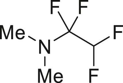
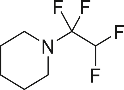
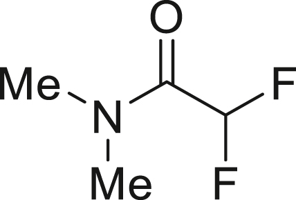
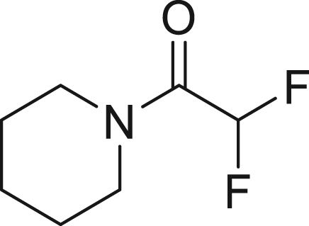
To further extend the utility of TFE, we scaled up its generation and explored amination reactions83,84 in an autoclave. TFE, produced from 10 mmol of HFC-125, was transferred to a THF solution containing 2.0 mmol of amine 7 at −85°C. The reaction mixture was gradually warmed to 0°C and left to stand for 12 h without stirring. When dimethylamine (7a) was used, the reaction proceeded quantitatively, yielding 1,1,2,2-tetrafluoro-N,N-dimethylethylamine (TFEDMA, 8a). The treatment of 8a with sat. NaHCO3 aq. afforded the corresponding amide derivative 9a in 80% yield. A similar reaction with piperidine (7b) produced piperidine-tetrafluoroethyl adduct 8b in 88% yield, which upon hydrolysis gave the amide 9b in 76% yield (Figure 4D).
Moreover, we examined the addition of alcohols85,86 to TFE (Figure 4E). Using a scale similar to that used for the amination reaction (Figure 4D), TFE was transferred to a diglyme solution containing 2.0 equiv of KOH and alcohols 10 (2.0 mmol) and stirred at 60°C for 16 h. The reaction with benzyl alcohol (10a) proceeded efficiently, delivering desired benzyl tetrafluoroethyl ether (11a) in 94% isolated yield. In the case of 1-hexanol (10b), the corresponding tetrafluoroethyl ether 11b was obtained in a moderate yield of 54% (isolated). The difference in yields between 10a and 10b can be explained by the higher nucleophilicity of 10a. The electron-donating nature of the benzyl group enhances nucleophilicity, leading to a more efficient alkoxylation process. These observations align well with previously reported findings.85,86
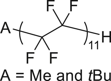
The radical polymerization87 of the generated TFE was initiated by tert-butyl peroxypivalate (TBPP) and conducted at 60°C for 8 h in acetone/solkane 365mfc within an autoclave. This process yielded 240 mg of the desired TFE polymer, X-CF2-(CF2-CF2)n-CF2-H (12, n = 11, X = Me and t-Bu), from 2.4 g of HFC-125 (Figure 4F). The 19F NMR spectrum closely matches that of an authentic PTFE sample, displaying a characteristic signal at −122 ppm along with three additional spinning side bands (Figure S5). Two additional terminal peaks were observed at −113 ppm (assigned to X-CF2-, where X = Me and t-Bu) and −138 ppm (assigned to –CF2H). The degree of polymerization (n = 11) was determined by comparing the integration of the main CF2 peak (−122 ppm) with the terminal CF2H peak (Figure S6).
Continuous flow synthesis of TFE
Finally, we sought to extend our bath transformation method for HFC-125 to TFE in a continuous flow process. The continuous flow approach offers significant advantages for large-scale chemical transformations, particularly when working with gaseous substrates,88,89,90 without requiring substantial modifications to reactor size. This method enables improvements in reaction conditions, such as drastically reduced reaction times and the elimination of cryogenic temperatures. Furthermore, it facilitates seamless scalability through continuous operation or parallelization, making it an ideal strategy for large-scale industrial applications.
We initially attempted the transformation of HFC-125 into TFE using a conventional micromixer, as employed in our previous work.58,59,60,91 However, this approach led to clogging of the flow path due to the precipitation of KF. To address this issue, we designed a new device in which HFC-125 is continuously bubbled into a KHMDS solution in toluene at room temperature while being vigorously stirred. The generated TFE is then continuously transferred into a nearby collector maintained at −85°C (Table 2). The flow rate of HFC-125 was controlled at 3.35 mL/min using a mass flow controller, while KHMDS, corresponding to 4.0 equivalents of HFC-125, was bubbled into a 1.0 M toluene solution. After bubbling for 5 min, resulting in an outflow of 0.75 mmol of HFC-125, the 19F NMR spectrum of the collected gas revealed no trace of HFC-125, with TFE obtained in 77% yield (entry 1). When the bubbling time was extended to 10 min (HFC-125: 1.50 mmol) with the same amount of KHMDS as in entry 1, 40% of TFE was produced, and 35% of HFC-125 remained (entry 2). Subsequently, increasing the amount of KHMDS to 3.0 equivalents led to the complete consumption of HFC-125 and a TFE yield of 97% (entry 3). This condition, using 3.0 equivalents of KHMDS relative to the outflow of HFC-125, also allowed for an extension of the bubbling time to 30 min (HFC-125: 4.50 mmol), achieving a nearly quantitative transformation to TFE (>99% yield) (entry 4). Finally, when the amount of KHMDS used in entry 1 was reduced to 3.0 equivalents and the bubbling was repeated for 5 min, TFE was obtained in 67% yield (entry 5). Thus, under the optimal conditions (>99% yield, 4.5 mmol of TFE, entry 4), scaling up within the current laboratory setup would enable increased production, yielding approximately 9 mmol (900 mg) of TFE in 1 h and 90 mmol (9 g) over 10 h. Furthermore, even larger production volumes could be achieved by utilizing a larger-scale continuous flow system.
Table 2.
Transformation of HFC-125 to TFE by a continuous flow process
 | |||||
|---|---|---|---|---|---|
| Entry | Flow time (min) | Total HFC-125 (x mmol) | KHMDS (y equiv) | Yield (%)a |
|
| HFC-125 | TFE | ||||
| 1 | 5 | 0.75 | 4.0 | 0 | 77 |
| 2 | 10 | 1.50 | 2.0 | 35 | 40 |
| 3 | 10 | 1.50 | 3.0 | 0 | 97 |
| 4 | 30 | 4.50 | 3.0 | 0 | >99 |
| 5 | 5 | 0.75 | 3.0 | 0 | 67 |
Yield was determined by19F NMR using C6F6 as the internal standard.
Our findings highlight that the stability and decomposition behavior of CF3CF2− are fundamentally governed by the steric and electronic properties of strong bases (e.g., KHMDS) and the solvent environment (ether vs. non-ether systems). Notably, the microflow process provides a distinct advantage, enabling highly selective and controlled decomposition to TFE at room temperature. This offers a practical and scalable approach for the conversion of HFC-125. By advancing the mechanistic understanding of CF3CF2− reactivity, this work contributes to the broader field of fluorine chemistry and supports the development of sustainable strategies for upcycling and repurposing HFCs in alignment with global environmental initiatives.
Conclusions
We have developed a highly efficient and scalable process for the conversion of HFC-125, a greenhouse gas, to TFE, an essential monomer for the fluoropolymer industry. Our method, using KHMDS at low temperatures, not only achieves high TFE yields but also effective of repurposing HFC-125. Meanwhile, fluoride is recovered to form KF. Moreover, the continuous flow conversion of HFC-125 to TFE was successfully achieved at ambient temperature without the need for cryogenic conditions during the reaction. However, low-temperature liquefaction was required for the efficient collection of gaseous TFE. Furthermore, we demonstrated the broad utility of this process, successfully applying TFE in a range of chemical reactions, including thiol addition, trifluorovinylation, radical addition, amination, alcohol addition and radical polymerization for TFE polymer, each yielding significant products with practical applications. Beyond its impact on the fluoropolymer industry, this straightforward process for generating TFE offers significant potential for medicinal chemistry. The ease of TFE production could inspire its use in late-stage fluoro-functionalization of drug derivatives containing SH, OH, or NH groups, a crucial advancement given the growing importance of fluoroorganic compounds in both the pharmaceutical92 and agrochemical sectors.93
The conventional production of TFE relies on the high-temperature pyrolysis of R-22, a process that requires significant energy input for both heating and cooling. In contrast, our method enables the conversion of HFC-125 to TFE under ambient conditions using a continuous flow system, presenting a potentially more energy-efficient and sustainable alternative. If successfully scaled up, this approach could not only reduce the energy burden associated with TFE production but also provide an environmentally responsible strategy for repurposing HFC-125—a hydrofluorocarbon subject to global regulatory phase-down. By addressing both the environmental challenges of HFC-125 and the increasing demand for TFE, this work contributes meaningfully to fluorine chemistry, building upon the milestone discovery of the “taming of fluoroform (HFC-23)94” in 2012. Moreover, the dehydrofluorination strategy employed here could be extended to other HFCs, enabling the synthesis of a broader range of fluoroolefins, which are essential intermediates in organofluorine chemistry. With the ongoing global efforts to phase down HFC emissions under the Kigali Amendment to the Montreal Protocol, our approach provides a sustainable and economically viable alternative to conventional disposal methods. Instead of incinerating HFCs and generating CO2 emissions, this upcycling strategy offers a pathway to convert stocked HFCs into valuable fluorochemicals, supporting a circular and environmentally conscious fluoropolymer industry.
Limitations of the study
While our method demonstrates broad applicability, from batch reactions to continuous flow processes, one current limitation lies in the collection and handling of the generated TFE. In industrial practice, TFE is typically stored and utilized as a compressed gas in high-pressure cylinders, which allows for precise pressure control during the subsequent fluoropolymer synthesis, such as the production of PTFE. In contrast, in our laboratory-scale setup, TFE is collected as a liquefied gas at low temperatures, which, while effective for small-scale chemical transformations, may limit its direct use in pressure-controlled polymerization processes. Therefore, establishing a safe and efficient method for collecting the generated TFE directly into a pressurized gas cylinder is a critical next step to fully realize the potential of this approach for sustainable fluoropolymer production at scale.
Resource availability
Lead contact
Further information and requests for resources and reagents should be directed to and will be fulfilled by the lead contact, Norio Shibata (nozshiba@nitech.ac.jp).
Materials availability
This study did not generate new unique reagents.
Data and code availability
-
•
All data supporting the results reported in this study are available within this paper and the supplemental information or from the lead contact upon request.
-
•
This paper does not report original code.
-
•
Any additional information required to reanalyze the data reported in this paper is available from the lead contact upon request.
Acknowledgments
This study was supported by the CREST program of the Japan Science and Technology Agency, entitled “Precise Material Science for Degradation and Stability” (grant number: JPMJCR21L1), and by Dr. Seiji Motojima (CMC Research Institute, Japan). J.E. thanks Universitat de València for financial support though the Fondo de investigación universitaria (FIU). J.E. also thanks the Advanced Materials programme (MFA/2022/051) supported by MCIN with funding from European Union NextGenerationEU (PRTR-C17.I1). The computational resources from the Servei d'Informàtica de la Universitat de València (SIUV) are gratefully acknowledged for providing access to supercomputing resources. We thank Mr. Yusuke Murata (Nagoya Institute of Technology) for his help with the reaction in Figure 4C.
Author contributions
Conceptualization, N.S.; methodology, H.I., N.H., Y.K., and N.S.; investigation, H.I.; analyses, H.I. and N.H.; DFT calculations, J.E.; discussion, H.I., N.H., Y.K., J.E., and N.S.; funding acquisition, N.S.; project administration, N.S.; supervision, N.S.; writing – original draft, H.I. and N.S.; writing – review and editing, N.S.
Declaration of interests
A patent application has been filed related to the research described in this manuscript.
Declaration of generative AI and AI-assisted technologies
During the preparation of this work, N.S. used Paperpal (editage) and DeepL in order to check the accuracy of the usage of the English language and the correction of the grammar. After using this tool or service, N.S. reviewed and edited the content as needed and takes full responsibility for the content of the publication.
STAR★Methods
Key resources table
| REAGENT or RESOURCE | SOURCE | IDENTIFIER |
|---|---|---|
| Chemicals, peptides, and recombinant proteins | ||
| Pentafluoromethane | Takachiho Chemical Industrial Co., Ltd. | CAS: 354-33-6 |
| Potassium bis(trimethylsilyl)amide | Sigma-Aldrich | CAS: 40949-94-8 Cat# 324671 |
| 4-tert-Butylbenzenethiol | TCI | CAS: 2396-68-1 Cat# B0741 |
| 2-Naphthalenethiol | TCI | CAS: 91-60-1 Cat# N0020 |
| Benzylmagnesium Chloride | Sigma-Aldrich | CAS: 6921-34-2 Cat# 225916 |
| Phenylmagnesium Bromide | Sigma-Aldrich | CAS: 100-58-3 Cat# 171565 |
| Lithium Chloride | Sigma-Aldrich | CAS: 7447-41-8 Cat# 203637 |
| 2,2′-Azobis(2,4-dimethylvaleronitrile) | TCI | CAS: 4419-11-8 Cat# A0680 |
| 2-(chlorotetrafluoro-l6-sulfaneyl)pyridine (5a) | Synthetized in our lab (Shibata et al.79) | https://doi.org/10.1002/anie.201605008 |
| 5-bromo-2-(chlorotetrafluoro-l6-sulfaneyl)pyridine (5b) | Synthetized in our lab (Shibata et al.79) | https://doi.org/10.1002/anie.201605008 |
| Dimethylamine | TCI | CAS: 124-40-3 Cat# D3948 |
| Piperidine | KANTO CHEMICAL CO., INC | CAS: 110-89-4 Cat# 32249-00 |
| Sodium Hydrogen Carbonate | NACALAI TESQUE, INC. | CAS: 144-55-8 Cat# 31212-12 |
| Benzyl Alcohol | TCI | CAS: 100-51-6 Cat# B2378 |
| 1-Hexanol | NACALAI TESQUE, INC. | CAS: 111-27-3 Cat# 18013-45 |
| Potassium Hydroxide | NACALAI TESQUE, INC. | CAS: 1310-58-3 Cat# 28616-45 |
| Diethylene Glycol Dimethyl Ether | TCI | CAS: 111-96-6 Cat# B0498 |
| tert-butyl peroxypivalate | NOF CORPORATION | CAS: 927-07-1 |
| Solkane®365mfc | NIPPON SOLVAY K.K. | CAS: 406-58-6 |
| Software and algorithms | ||
| Gaussian16 | Frisch et al.95 | RRID:SCR_014897; https://gaussian.com/ |
| CYLview20 | Legault, C. Y.96 | http://www.cylview.org |
Experimental model and study participant details
This study did not use experimental models typical in life sciences.
Method details
General information
Chemicals
Commercially available chemicals were obtained from Aldrich Chemical Co., Nacalai tesque, TCI, Wako and used as received unless otherwise stated. HFC-125 was purchased from Takachiho Chemical Industrial Co., Ltd. and used. The pure gaseous TFE supplied by Daikin Industries, Ltd. was used. tert-butyl peroxypivalate was given by NOF CORPORATION.
Solvents
All solvents were dehydrated and degassed and transferred with a syringe.
Column chromatography
Column chromatography was performed on silica gel 60N spherical neutral size, 64−210 μm (FUJIFILM Wako).
Nuclear magnetic resonance spectroscopy
NMR spectra were recorded on a Varian Mercury 300 spectrometer for 1H NMR (300 MHz) and 19F NMR (282 MHz), and a Bruker Avance 500 for 1H NMR (500 MHz) and 13C{1H} NMR (125 MHz) and a JEOL RESONANCE ECZ700R for 1H NMR (700 MHz). In 19F NMR experiments, Magritek Spinsolve60 (60 MHz) was used. Solid-state NMR was measured using JEOL JNM-ECA600 (600 MHz). The chemical shifts (δ) were measured in parts per million with respect to solvent (1H: TMS, δ = 0.00 ppm, 19F: CDCl3, δ = −162.2 ppm with C6F6 as internal standard; 13C{1H}: CDCl3, δ = 77.16 ppm), and coupling constants (J) are given in hertz. The following abbreviations denoted the corresponding multiplicities: s, singlet; d, doublet; t, triplet; q, quadruplet; dd, doublet of doublets; td, triplet of doublets; dt, doublet of triplets; m, multiplet; br, broad.
Mass spectrometry
Mass spectra were recorded using a JEOL JMS-Q1050GC (EI−GCMS) system and LCMS-2020EV (ESI-MS) system. High−resolution mass spectrometry (HRMS) was performed on a Waters Synapt G2 HDMS (ESI−TOF−MS) instrument.
Infrared absorption spectrometry
Infrared spectra were recorded using a JASCO FT/IR−6300 spectrometer.
Melting points
Melting points were determined using a BUCHI M−565 apparatus.
Cooling and heating source
A Techno Sigma UC Reactor was used as a cooling source. An oil bath was used as a heating source.
Reaction
All reactions were performed under an inert gas atmosphere unless otherwise noted.
Components of flow system
A mass flow controller (Fujikin, FCST1005MLC) was used to control the flow rate of gaseous HFC-125. The pressure of HFC-125 was regulated by the regulator connected to the HFC-125 cylinder. All flow apparatus (grass vials, stir bar, rubber septum, tubes) were dried and filled with N2 gas prior to use. A ETFE tube (inner diameter: 1.0 mm) was used for the gas flow path.
Experimental procedure and characterization
Procedure for determination of the yield of tetrafluoroethylene
In the glove box, a solution of toluene in which KHMDS was dissolved to make 0.25 M was prepared and a defined amount was transferred to an NMR tube. Toluene-d 8 was added to make a total volume of 0.7 mL, followed by 1.14 μL (0.01 mmol) of hexafluorobenzene as an internal standard. The NMR tube was covered with a septum cap, sealed with parafilm, and removed from glove box. The mixture was frozen in liquid nitrogen and vacuumed. HFC−125 was removed from the gas cylinder into a balloon and 0.56 mL (0.025 mmol) was injected under liquid nitrogen using a gastight syringe. While the lower part of the tube was immersed in liquid nitrogen, the upper part of the tube was warmed by hand to melt HFC−125 down to the solution interface. The mixture was moved to a low temperature methanol bath at −50°C and stirred vigorously for 3 h. The sample was moved to a low temperature methanol bath at −90°C and allowed to stand for 1 h, after which 19F NMR was measured while maintaining the temperature as low as possible to obtain the integrated value.
General procedure 1: Generation of tetrafluoroethylene
In the glove box, KHMDS (1.5 equiv) and stirrer tip were placed in a vacuum sample tube (chamber A) and dissolved in 3.0 mL of toluene. The tube was closed with a Teflon screw cap, a septum cap attached to the side arm, removed from the glow box and immersed in liquid nitrogen to freeze the solution. The inside of the container was vacuumed, and a predetermined amount of HFC−125 (1.0 equiv) was injected from the side tube side using a gas tight syringe (Figure S7). The mixture was moved to a low temperature bath at −50°C and stirred vigorously for 3 h.
General procedure 2: Hydrothiolation of TFE using thiol

TFE was synthesized according to general procedure 1. Thiol 1 (0.5 mmol, 1.0 equiv), 12.3 μL PhCF3 (0.1 mmol) as an internal standard and stirrer tip were added to another oven−dried vacuum sample tube (chamber B) under a nitrogen atmosphere, dissolved in 3.0 mL of dry N,N-Dimethylacetamide (DMA), and sealed with a Teflon screw cap. The solution was frozen by immersion in liquid nitrogen, and the interior was decompressed. The side arms of chambers A and B were connected with a silicon tube, and the cap was opened slightly while the chamber B was immersed in liquid nitrogen (Figure S8). Then, the cap of the chamber A was opened slowly, and the TFE was transferred. Once the transfer was complete, all caps were closed and the silicone tube removed and the top of chamber B warmed to drop the TFE to the solution interface. The mixture was warmed up to room temperature and left to rest for 3 h. The reaction mixture was poured into 30 mL of water and extracted with Et2O (5 mL × 3). The combined organic layers were washed with Brine and dried over Na2SO4. The solvent was removed under reduced pressure with a rotary evaporator and the residue was purified by flash silica gel column chromatography to give compound 2.
Scale-up synthesis of 2a using autoclave
In the glove box, 18 mmol KHMDS (9.0 equiv), stirrer tip and 6.0 mL of toluene were added to a flame dried autoclave vessel and stirred vigorously. The autoclave was covered in a glove box before being removed and immersed in liquid nitrogen to freeze the solution. 1440 mg HFC−125 (12 mmol, 6.0 equiv) was injected while cooling with liquid nitrogen by reducing the internal pressure with a vacuum pump. The mixture was moved to a methanol bath at −50°C and stirred vigorously for 3 h. Thiol 1a (334.8 mg, 2.0 mmol), stirrer tip, hexafluorobenzene 115 μL (1.0 mmol) as an internal standard and 12 mL dry DMA were added to a flame − dried autoclave with bubbling lines under argon atmosphere. It was tightly closed and cooled to −85°C. The autoclave which produced the TFE was removed from the cold bath and connected to the bubbling line. The pressure in the autoclave at the transfer destination was quickly reduced (Figure S9A). The line cock was slowly opened and TFE was slowly bubbled at −85°C over 1 h (Figure S9B). After the transfer was completed, the mixture was warmed to room temperature and left to rest for 3 h. The cock was opened to purge excess TFE in the draft. The reaction mixture was poured into 50 mL of water and extracted with Et2O (10 mL × 3). The combined organic layers were washed with Brine and dried over Na2SO4. The solvent was removed under reduced pressure with a rotary evaporator and the residue was purified by flash silica gel column chromatography (nHexane) to give compound 2a (517.3 mg, 97%).
(4-(tert-butyl)phenyl)(1,1,2,2-tetrafluoroethyl)sulfane (2a)
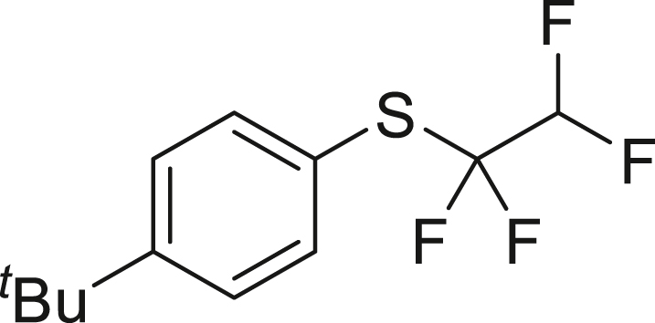
HFC-125(3.0 mmol, 67. 2 mL) and KHMDS (4.5 mmol, 897.7 mg) were transformed to TFE following general procedure 1. 2a was obtained using 1a (82.4 mg, 0.5 mmol) by following general procedure 2. Purification by column chromatography on silica gel (nhexane) to give 2a (119.2 mg, 90%) as a colorless oil.
1H NMR (300 MHz, chloroform-d) δ: 7.57 (d, J = 8.5 Hz, 2H), 7.42 (d, J = 8.5 Hz, 2H), 5.76 (tt, 1J = 53.7 Hz, 2J = 3.6 Hz, 1H), 1.33 (s, 9H) ppm. 19F NMR (282 MHz, chloroform-d) δ: −93.0 (td, 1J = 9.7 Hz, 2J = 3.3 Hz, 2F), −133.5 (dt, 1J = 53.8 Hz, 2J = 9.4 Hz, 2F) ppm. MS (EI) m/z: [M]+ 266.0. Analytical data are consistent with reported values.77
naphthalen-2-yl(1,1,2,2-tetrafluoroethyl)sulfane (2b)

HFC-125(67.2 mL, 3.0 mmol) and KHMDS (897.7 mg, 4.5 mmol) were transformed to TFE following general procedure 1. 2b was obtained using 1b (79.7 mg, 0.5 mmol) by following general procedure 2. Purification by column chromatography on silica gel (nhexane) to give 2b (105.4 mg, 81%) as a colorless oil.
1H NMR (300 MHz, chloroform-d) δ: 8.21 (s, 1H), 7.87 (d, J = 8.6 Hz, 3H), 7.67-7.54 (m, 3H), 5.80 (tt, 1J = 53.8 Hz, 2J = 3.4 Hz, 1H) ppm. 19F NMR (282 MHz, chloroform-d) δ: −92.2 (td, 1J = 9.4 Hz, 2J = 3.3 Hz, 2F), −133.5 133.0 (dt, 1J = 53.8 Hz, 2J = 9.2 Hz, 2F) ppm. MS (EI) m/z: [M]+ 260.0. Analytical data are consistent with reported values.77
General procedure 3: Trifluoro-vinylation with Grignard reagent

TFE was synthesized according to general procedure 1. In the glove box, lithium chloride (0.6 mmol, 1.2 equiv), Grignard reagent 3 (0.5 mmol, 1.0 equiv), 12.3 μL PhCF3 (0.1 mmol) as an internal standard and stirrer tip were added to another oven−dried vacuum sample tube (chamber B) and dissolved in 3.0 mL of dry THF and stirred at room temperature. It was sealed with a Teflon screw cap and removed from glove box. The solution was frozen by immersion in liquid nitrogen, and the interior was decompressed. The side arms of chambers A and B were connected with a silicon tube, and the cap was opened slightly while the chamber B was immersed in liquid nitrogen. Then, the cap of the chamber A was opened slowly, and the TFE was transferred. Once the transfer was complete, all caps were closed and the silicone tube removed and the top of chamber B warmed to drop the TFE to the solution interface. The temperature was raised to room temperature and left to rest for a predetermined time. The yield of compound 4 was determined by 19F NMR.
(2,3,3-trifluoroallyl)benzene (4a)
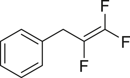
HFC-125(67.2 mL, 3.0 mmol) and KHMDS (897.7 mg, 4.5 mmol) were transformed to TFE following general procedure 1. Following general procedure 3, benzyl magnesium chloride (3a; in 2.0 M THF solution, 0.25 mL, 0.5 mmol) and LiCl (25.4 mg, 0.6 mmol) gave the title compound in >99% yield by placing still without stirring for 3 h. 19F NMR (282 MHz, chloroform-d) δ: −105.6 (dd, 1J = 85.7 Hz, 2J = 32.2 Hz, 1F), −124.5 (dd, 1J = 114.6 Hz, 2J = 85.9 Hz, 1F), −172.9 (ddt, 1J = 114.8 Hz, 2J = 41.4, 3J = 16.1 Hz, 1F). MS (EI) m/z: [M]+ 172.0. Analytical data are consistent with reported values.78
(1,2,2−trifluorovinyl)benzene (4b)

HFC-125(112.0 mL, 5.0 mmol) and KHMDS (1496.1 mg, 7.5 mmol) were transformed to TFE in 4.0 mL of toluene following general procedure 1. Following general procedure 3, phenyl magnesium bromide (3b; in 3.0 M Diethyl ether solution, 0.2 mL, 0.6 mmol) and LiCl (30.5 mg, 0.72 mmol) gave the title compound in 74% yield by placing still without stirring for 3 days 19F NMR (282 MHz, chloroform-d) δ: −100.3 (dd, 1J = 71.3 Hz, 2J = 32.7 Hz, 1F), −115.1 (dd, 1J = 110.0 Hz, 2J = 71.3 Hz, 1F), −177.2 (dd, 1J = 109.0 Hz, 2J = 32.7 Hz, 1F). MS (EI) m/z: [M]+ 158.0. Analytical data are consistent with reported values.97
General procedure 4: Radical addition of PySF4Cl

TFE was synthesized according to general procedure 1. In the glove box, PySF4Cl 5 (0.5 mmol, 1.0 equiv), stirrer tip and ADVN (0.05 mmol, 10 mol%) were added to another oven−dried vacuum sample tube (chamber B) and dissolved in 2.0 mL of dry ethyl acetate. It was sealed with a Teflon screw cap and removed from glove box. The solution was frozen by immersion in liquid nitrogen, and the interior was decompressed. The side arms of chambers A and B were connected with a silicon tube, and the cap was opened slightly while the chamber B was immersed in liquid nitrogen. Then, the cap of the chamber A was opened slowly, and the TFE was transferred. Once the transfer was complete, all caps were closed and the silicone tube removed and the top of chamber B warmed to drop the TFE to the solution interface. The mixture was warmed up to 40°C and stirred at same temperature for 3 days. The solvent was removed under reduced pressure with a rotary evaporator and the residue was purified by flash silica gel column chromatography to give compound 6.
2-((2-chloro-1,1,2,2-tetrafluoroethyl)tetrafluoro-λ6-sulfaneyl)pyridine (6a)
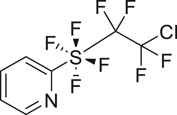
HFC-125(67.2 mL, 3.0 mmol) and KHMDS (897.7 mg, 4.5 mmol) were transformed to TFE following general procedure 1. 6a was obtained using 5a (117.1 mg, 0.5 mmol) and ADVN (12.4 mg, 0.05 mmol) by following general procedure 4. Purification by silica gel column chromatography (nhexane/AcOEt = 20/1) to give 6a (85.9 mg, 51%) as a colorless oil. 1H NMR (300 MHz, CDCl3) δ: 8.60 (d, J = 3.2 Hz, 1H), 7.94 (t, J = 7.9 Hz, 1H), 7.78 (d, J = 8.2 Hz, 1H), 7.51 (dd, 1J = 7.3 Hz, 2J = 4.7 Hz, 1H) ppm 19F NMR (282 MHz, CDCl3) δ: 37.5–37.3 (m, 4F), −67.9–−68.1 (m, 2F), −91.1–−91.3 (m, 2F) ppm. MS (EI) m/z: [M + Na]+ 321.0. Analytical data are consistent with reported values.82
5-bromo-2-((2-chloro-1,1,2,2-tetrafluoroethyl)tetrafluoro-λ6-sulfaneyl)pyridine (6b)

HFC-125(67.2 mL, 3.0 mmol) and KHMDS (897.7 mg, 4.5 mmol) were transformed to TFE following general procedure 1. 6b was obtained using 5b (180.3 mg, 0.6 mmol) and ADVN (14.9 mg, 0.06 mmol) by following general procedure 4. Purification by silica gel column chromatography (nhexane/AcOEt = 20/1) to give 6b (179.6 mg, 76%) as a pale-blown solid. 1H NMR (300 MHz, CDCl3) δ: 8.63 (d, J = 2.1 Hz, 1H), 8.05 (d, J = 8.5 Hz, 1H), 7.68 (d, J = 8.8 Hz, 1H) ppm 13C {1H} NMR (126 MHz, CDCl3) δ: 165.0 (quint, J = 25.2 Hz), 149.1, 141.4, 124.1, 122.8 (t, J = 4.1 Hz), 122.2 (tt, 1J = 303.8 Hz, 2J = 35.4 Hz), 121.0 (tquint, 1J = 321.3 Hz, 2J = 37.3 Hz) ppm 19F NMR (282 MHz, CDCl3) δ: 38.6–38.4 (m, 4F), −68.1–−68.2 (m, 2F), −91.1–−91.3 (m, 2F) ppm. FT-IR (KBr): ν = 3056, 2924, 1567, 1451, 1366, 1210, 1138, 800, 664 cm-1. m.p.: 50.3°C–51.3°C. HRMS (ESI) m/z: [M + Na]+ calcd. for C7H3ClF8NSNa; 421.8628 Found 421.8629.
General procedure 5: Addition reaction of amines using TFE

In the glove box, 12 mmol KHMDS (6.0 equiv) and stirrer tip and 6.0 mL of toluene were added to a flame dried autoclave vessel and stirred vigorously. The autoclave was covered in a glove box before being removed and immersed in liquid nitrogen to freeze the solution. 1200 mg HFC−125 (10 mmol, 5.0 equiv) was injected while cooling with liquid nitrogen by reducing the internal pressure with a vacuum pump. The mixture was moved to a methanol bath at −50°C and stirred vigorously for 3 h. Amine 7 (2.0 mmol, 1.0 equiv), hexafluorobenzene 115 μL (1.0 mmol) as an internal standard and 5 mL THF were added to a flame−dried autoclave with bubbling lines under argon atmosphere. It was tightly closed and cooled to −94°C. The autoclave which produced the TFE was removed from the cold bath and connected to the bubbling line. The pressure in the autoclave at the transfer destination was quickly reduced. The line cock was slowly opened and TFE was slowly bubbled at −94°C over 1 h. After the transfer was completed, the temperature of the bath was slowly raised to 0°C over 3 h and placed still without stirring at 0°C for 12 h. After the mixture was warmed up to room temperature, the cock was opened to purge excess TFE in the draft. The yield of compound 8 was determined by 19F NMR. The saturated aqueous NaHCO3 (10 mL) was added dropwise to the mixture at 0°C. and stirred at room temperature for 2 h. The aqueous layer was extracted with Et2O, and the combined organic layers were washed with brine, dried over Na2SO4. The organic layer was concentrated under reduced pressure and dried in vacuo. The amide compound 9 was obtained without further purification.
1,1,2,2–tetrafluoro–N, N–dimethylethan–1–amine (8a)
Following the general procedure 5, Dimethylamin (7a; in 2.0 M THF solution, 1.0 mL, 2.0 mmol, 1.0 equiv) gave the title compound in >99% yield.
19F NMR (282 MHz, chloroform-d) δ −102.5 (s, 2F), −134.0 (dt, 1J = 53.2 Hz, 2J = 6.2 Hz, 2F) ppm. MS (EI), m/z: [M]+ 145.0. Analytical data are consistent with reported values.83
1-(1,1,2,2-tetrafluoroethyl)piperidine (8b)
Following the general procedure 5, piperidine 7b (170.3 mg, 2.0 mmol, 1.0 equiv) gave the title compound in 88% yield.
19F NMR (282 MHz, chloroform-d) δ −100.4 (s, 2F), −134.0 (dt, 1J = 53.2 Hz, 2J = 6.4 Hz, 2F) ppm. Analytical data are consistent with reported values.98
2,2-difluoro-N, N-dimethylacetamide (9a)
Treatment of a mixture of 8a with sat. NaHCO3 aq. according to general procedure 5 gave 9a (198.0 mg, 80%) as a yellow oil.
1H NMR (700 MHz, chloroform-d) δ: 6.11 (t, J = 53.7 Hz, 1H), 3.14 (t, J = 1.4 Hz, 3H), 3.01 (t, J = 1.0 Hz, 3H) ppm 19F NMR (282 MHz, chloroform-d) δ: −122.2 (d, J = 54.1 Hz, 2F) ppm. MS (EI) m/z: [M]+ 123.0. Analytical data are consistent with reported values.99
2,2-difluoro-1-(piperidin-1-yl)ethan-1-one (9b)
Treatment of a mixture of 8a with sat. NaHCO3 aq. according to general procedure 5 gave 9b (247.7 mg, 76%) as a yellow oil.
1H NMR (300 MHz, chloroform-d) δ: 6.11 (t, J = 53.8 Hz, 1H), 3.59-3.54 (m, 4H), 1.66-1.61 (m, 6H) ppm. 13C {1H} NMR (126 MHz, CDCl3) δ: 160.5 (t, J = 25.0 Hz), 110.6 (t, J = 253.8 Hz), 45.9 (t, J = 4.1 Hz), 43.7, 26.4, 25.4, 24.3 ppm. 19F NMR (282 MHz, chloroform-d) δ: −121.7 (d, J = 53.5 Hz, 2F) ppm. FT-IR (NaCl): ν = 2944, 2857, 1671, 1447, 1378, 1254, 1117, 1056, 856 cm-1. HRMS (ESI) m/z: [M + Na]+ calcd. for C7H11F2NONa; 186.0706 Found 186.0705.
General procedure 6: Addition reaction of alcohols using TFE

12 mmol KHMDS (6.0 equiv), stirrer tip and 6.0 mL of toluene were added to a flame dried autoclave vessel and stirred vigorously. The autoclave was covered in a glove box before being removed and immersed in liquid nitrogen to freeze the solution. 1200 mg HFC−125 (10 mmol, 5.0 equiv) was injected while cooling with liquid nitrogen by reducing the internal pressure with a vacuum pump. The mixture was moved to a methanol bath at −50°C and stirred vigorously for 3 h. Alcohol 10 (2.0 mmol, 1.0 equiv), stirrer tip, potassium hydroxide (4.0 mmol, 2.0 equiv), hexafluorobenzene 115 μL (1.0 mmol) as an internal standard and 10 mL dry Diglyme were added to a flame − dried autoclave with bubbling lines under argon atmosphere. It was tightly closed and cooled to −85°C. The autoclave which produced the TFE was removed from the cold bath and connected to the bubbling line. The pressure in the autoclave at the transfer destination was quickly reduced. The line cock was slowly opened and TFE was slowly bubbled at −85°C over 1 h. After the transfer was completed, the mixture was warmed to 60°C with oil bath and stirred slowly for 16 h. After the mixture was cooled to room temperature, the cock was opened to purge excess TFE in the draft. The mixture was quenched with aqueous ammonium chloride and extracted with 30 mL of water and Et2O (5 mL × 3). The combined organic layers were washed with Brine and dried over Na2SO4. The solvent was removed under reduced pressure with a rotary evaporator and the residue was purified by flash silica gel column chromatography to give the alcohol adduct 11.
((1,1,2,2-tetrafluoroethoxy) methyl) benzene (11a)

11a was obtained using 10a (218.5 mg, 2.0 mmol) and KOH (224.4 mg, 4.0 mmol) by following general procedure 6. Purification by column chromatography on silica gel (nhexane/ethyl acetate = 98/2) to give 11a (392.1 mg, 94%) as a colorless oil.
1H NMR (300 MHz, chloroform-d) δ: 7.42-7.38 (m, 5H), 5.75 (tt, 1J = 53.3 Hz, 2J = 2.9 Hz, 1H), 5.01 (s, 2H) ppm 19F NMR (282 MHz, chloroform-d) δ: −91.5 (td, 1J = 5.9 Hz, 2J = 2.9 Hz, 2F), −137.0 (dt, 1J = 53.5 Hz, 2J = 5.9 Hz, 2F) ppm. MS (EI) m/z: [M]+ 208.0. Analytical data are consistent with reported values.100
1-(1,1,2,2-tetrafluoroethoxy)hexane (11b)

11b was obtained using 10b (204.0 mg, 2.0 mmol) and KOH (224.4 mg, 4.0 mmol) by following general procedure 6. Purification by short open column chromatography on silica gel (npentane) to give 11b (216.1 mg, 54%) as a colorless oil.
1H NMR (300 MHz, chloroform-d) δ: 5.69 (tt, 1J = 53.4 Hz, 2J = 2.8 Hz, 1H), 3.97 (t, J = 6.6 Hz, 2H), 1.72-1.62 (m, 2H), 1.40-1.26 (m, 6H), 0.90 (t, J = 6.7 Hz, 3H) ppm. 13C {1H} NMR (126 MHz, CDCl3) δ: 117.5 (tt, 1J = 267.0 Hz, 2J = 28.2 Hz), 110.3-105.7 (m), 64.8-64.6 (m), 31.4, 29.0, 25.4, 22.6, 14.1 ppm 19F NMR (282 MHz, chloroform-d) δ: −91.9 (td, 1J = 5.9 Hz, 2J = 3.0 Hz, 2F), −137.2 (dt, 1J = 53.5, 2J = 5.9 Hz, 2F) ppm. FT-IR (NaCl): ν = 2961, 2932, 2862, 1277, 1219, 1124, 1084 cm-1. LCMS (ESI) m/z: [M + H]+ 203.10.
General procedure 7: Radical polymerization of the generated TFE

6 g KHMDS (30 mmol, 1.5 equiv), stirrer tip and 16.0 mL of toluene were added to a flame dried autoclave vessel and stirred vigorously. The autoclave was covered in a glove box before being removed and immersed in liquid nitrogen to freeze the solution. 2.4 g HFC−125 (20 mmol, 1.0 equiv) was injected while cooling with liquid nitrogen by reducing the internal pressure with a vacuum pump. The mixture was moved to a methanol bath at −50°C and stirred vigorously for 3 h. After 3 h, the mixture was removed from the methanol bath and allowed to warm to room temperature. A stirrer tip, 49.8 mg tert-butyl peroxypivalate (71% hydrocarbon dilution solution, 0.01 equiv), 12 mL degassed acetone and 3.0 mL Solkane-365mfc were added to a flame − dried another autoclave reactor with bubbling line at 0°C under nitrogen atmosphere. This mixture was bubbled with nitrogen at 0°C for 30 min. The reactor was evacuated and backfilled with nitrogen 4 times at 0°C. The reactor was evacuated again, and the autoclaves were connected. While the autoclave reactor for polymerization was cooled to −85°C, the valve was opened slowly to transfer the generated TFE. After the transfer was completed, the mixture was allowed to warm to 60°C with oil bath and stirred for 8 h. After the pressure stopped decreasing, the mixture was cooled to room temperature and de-pressurized to remove excess TFE in the draft. The solid product was filtered by vacuum and washed with acetone. The white solid was dried under vacuum to give the title compound 12.
Polytetrafluoroethylene (12)
The title compound 12 (n = 11, 240 mg) was obtained as a white solid following general procedure 7.
1H NMR (600 MHz) δ: 6.00 (s, 1H), 1.36-1.08 (br) ppm. 13C {1H} NMR (151 MHz) δ: 111.5 ppm 19F NMR (565 MHz) δ: −112.7 (br, 2F), −122.1 (s, 38F), −130.3 (br, 2F), −138.3 (s, 2F) ppm.
General procedure for continuous flow synthesis of TFE

A 1.0 M KHMDS (3.0 equiv) -anhydrous toluene solution (reaction vessel) was prepared in a glove box oven-dried vial (5 min & 10 min: 10 mL, 30 min: 25 mL) based on the outflow time (5 min: 0.75 mmol, 10 min: 1.5 mmol, 30 min: 4.5 mmol) of HFC-125. A toluene solution (5min: 20 mL, 10 min: 23 mL, 30 min: 45 mL) with hexafluorobenzene (5 min: 0.1 mmol, 10 min & 30 min: 1.0 mmol) as an internal standard was prepared in a screw vial (5min & 10 min: 25 mL, 30 min: 50 mL) (collection vessel). The flow line as shown in Figure S10 was assembled under nitrogen atmosphere. At this time, each gas outlet was placed above the liquid surface, and the collection vessel was opened by inserting a needle. HFC-125 was flowed at a rate of 3.35 mL/min through a mass flow controller at a pressure of 0.1 MPa from a cylinder of HFC-125. The outlet of the HFC-125 outflow tube was immersed in the solution of the reaction vessel and bubbled. The reaction was started by vigorous stirring at room temperature. After exhausting the gas for 1 minute, the needle inserted into the collection vessel was removed to make a closed system. Immediately, the outlet of the outflow tube on the collection vessel side was immersed in toluene cooled to −85°C, and collection of TFE started. After the HFC-125 was continued to flow for a predetermined time (5 min or 10 min or 30 min), the flow of HFC-125 was stopped and the mixture was stirred at room temperature for another 5 minutes (Figure S11A). After no bubbles were generated, the tube tip of the collection vessel was removed from the toluene, and the collection vessel was immersed in liquid nitrogen to completely remove the gases in the reaction vessel (Figure S11B). After no bubbles were generated from the reactor, the collection vessel was closed tightly with a screw cap and immersed in a methanol bath at −85°C. After standing in a methanol bath at −85°C for 1 h, the mixture was quickly taken into an NMR tube previously cooled to −85°C, and 19F NMR was measured to determine the yield.
Quantification and statistical analysis
Computational details
All density functional theory (DFT) calculations were carried out using the Gaussian16 package.95 All the structures were optimized using the long-range corrected hybrid ωB97xD density functional101 in combination with the Def2TZVP basis set.102 The effect of the solvent was mimicked by applying the SMD model using ether as solvent.103 The nature of the stationary points was confirmed by frequency calculations analysis at the same level of theory (minima were characterized by no imaginary frequencies, whereas transition states had one imaginary frequency). Transition states were further verified by relaxing the imaginary frequency towards the reactant and the product and by means of IRC calculations.104 3D structures of optimized stationary points were represented using the CYLview 1.0 program.96
Published: May 3, 2025
Footnotes
Supplemental information can be found online at https://doi.org/10.1016/j.isci.2025.112580.
Supplemental information
References
- 1.Wilson L.C., Wilding W.V., Wilson G.M., Rowley R.L., Felix V.M., Chisolm-Carter T. Thermophysical Properties of HFC-125. Fluid Phase Equilib. 1992;80:167–177. doi: 10.1016/0378-3812(92)87065-U. [DOI] [Google Scholar]
- 2.Yang Z., Liu H., Wu X. Theoretical and Experimental Study of the Inhibition and Inert Effect of HFC125, HFC227ea and HFC13I1 on the Flammability of HFC32. Process Saf. Environ. Prot. 2012;90:311–316. doi: 10.1016/j.psep.2011.09.009. [DOI] [Google Scholar]
- 3.Nagy B., Csontos B., Csontos J., Szakács P., Kállay M. High-Accuracy Theoretical Thermochemistry of Fluoroethanes. J. Phys. Chem. A. 2014;118:4824–4836. doi: 10.1021/jp503492a. [DOI] [PubMed] [Google Scholar]
- 4.Rusch G.M. The Development of Environmentally Acceptable Fluorocarbons. Crit. Rev. Toxicol. 2018;48:615–665. doi: 10.1080/10408444.2018.1504276. [DOI] [PubMed] [Google Scholar]
- 5.McCulloch A. CFC and Halon Replacements in the Environment. J. Fluor. Chem. 1999;100:163–173. doi: 10.1016/S0022-1139(99)00198-0. [DOI] [Google Scholar]
- 6.Velders G.J.-M., Ravishankara A.R., Miller M.K., Molina M.J., Alcamo J., Daniel J.S., Fahey D.W., Montzka S.A., Reimann S. Preserving Montreal Protocol Climate Benefits by Limiting HFCs. Science. 2012;335:922–923. doi: 10.1126/science.1216414. [DOI] [PubMed] [Google Scholar]
- 7.Flerlage H., Velders G.J.M., de Boer J. A review of Bottom-up and Top-down Emission Estimates of Hydrofluorocarbons (HFCs) in Different parts of the World. Chemosphere. 2021;283 doi: 10.1016/j.chemosphere.2021.131208. [DOI] [PubMed] [Google Scholar]
- 8.Miranda N.D., P.-Alcantar P.G., Khosla R., McCulloch M.D. Metrics for the Emissions of F-gas Refrigerants. Sustain. Energy Technol Assess. 2023;58 doi: 10.1016/j.seta.2023.103348. [DOI] [Google Scholar]
- 9.Liu H., Duan H., Zhang N., Ma Y., Liu G., Miller T.R., Mao R., Xu M., Li J., Yang J. Rethinking Time-Lagged Emissions and Abatement Potential of Fluorocarbons in the Post-Kigali Amendment Era. Nat. Commun. 2024;15:6687. doi: 10.1038/s41467-024-51113-2. [DOI] [PMC free article] [PubMed] [Google Scholar]
- 10.U.S. Environmental Protection Agency Home Page Protecting Our Climate by Reducing Use of HFCs. 2024. https://www.epa.gov/climate-hfcs-reduction
- 11.Acerboni G., Beukes J.A., Jensen N.R., Hjorth J., Myhre G., Nielsen C.J., Sundet J.K. Atmospheric Degradation and Global Warming Potentials of Three Perfluoroalkenes. Atmos. Environ. X. 2001;35:4113–4123. doi: 10.1016/S1352-2310(01)00209-6. [DOI] [Google Scholar]
- 12.Siegemund G., Schwertfeger W., Feiring A., Smart B., Behr F., Vogel H., McKusick B., Kirsch P. Ullmann's Encyclopedia of Industrial Chemistry. Wiley-VCH Verlag GmbH & Co. KgaA; 2016. Fluorine Compounds, Organic; pp. 18–20. [DOI] [Google Scholar]
- 13.Downing F.B., Benning A.F., McHarness R.C. Pyrolysis of Chloro-fluoro Alkanes. U. S. Patent US2551573. 1945 filed November 30, 1945, and granted May 08, 1951. [Google Scholar]
- 14.Chinoy P.B., Sunavala P.D. Thermodynamics and Kinetics for the Manufacture of Tetrafluoroethylene by the Pyrolysis of Chlorodifluoromethane. Ind. Eng. Chem. Res. 1987;26:1340–1344. doi: 10.1021/ie00067a013. [DOI] [Google Scholar]
- 15.Farlow M.W. Method for the Preparation of Tetrafluoroethylene. U. S. Patent US3081245. 1963 filed March 17, 1960, and granted March 12, 1963. [Google Scholar]
- 16.Tress W.R.W. Preparation of Tetrafluoroethylene. U. S. Patent US3133871. 1964 filed January 11, 1963, and granted May 19, 1964. [Google Scholar]
- 17.Park J., Benning A., Downing F., Laucius J., McHarness R. Synthesis of Tetrafluorethylene-Pyrolisis of Monochlorodifluoromethane. Ind. Eng. Chem. 1947;39:354–358. doi: 10.1021/ie50447a624. [DOI] [Google Scholar]
- 18.Sung D.J., Moon D.J., Lee Y.J., Hong S.-I. Catalytic Pyrolysis of Difluorochloromethane to Produce Tetrafluoroethylene. Int. J. Chem. Reactor Eng. 2004;2:1–8. doi: 10.2202/1542-6580.1065. [DOI] [Google Scholar]
- 19.Yang G.-C., Jia X.-Q., Pan R.-M., Quan H.-D. The Disproportionation of CF2 Carbene in Vapor-Phase Pyrolysis Reaction over Activated Carbon and Porous Aluminum Fluoride. J. Mol. Catal. A: Chem. 2009;309:184–188. doi: 10.1016/j.molcata.2009.06.003. [DOI] [Google Scholar]
- 20.Timperley C.M. Chapter 29 - Highly-Toxic Fluorine Compounds. Fluorine Chemistry at the Millennium. 2000:499–538. doi: 10.1016/B978-008043405-6/50040-2. [DOI] [Google Scholar]
- 21.Smith L.W., Gardner R.J., Kennedy G.L., Jr. Short-Term Inhalation Toxicity of Perfluoroisobutylene. Drug Chem. Toxicol. 1982;5:295–303. doi: 10.3109/01480548209041059. [DOI] [PubMed] [Google Scholar]
- 22.Wang H., Ding R., Ruan J., Yuan B., Sun X., Zhang X., Yu S., Qu W. Perfluoroisobutylene-Induced Acute Lung Injury and Mortality are Heralded by Neutrophil Sequestration and Accumulation. J. Occup. Health. 2001;43:331–338. doi: 10.1539/joh.43.331. [DOI] [Google Scholar]
- 23.Patocka J. Perfluoroisobutene: Poisonous Choking Gas. Mil. Med. Sci. Lett. 2019;88:98–105. doi: 10.31482/mmsl.2019.006. [DOI] [Google Scholar]
- 24.Timperley C.M. Fluoroalkene Chemistry: Part 1. Highly-Toxic Fluorobutenes and their Mode of Toxicity: Reactions of Perfluoroisobutene and Polyfluorinated Cyclobutenes with Thiols. J. Fluor. Chem. 2004;125:685–693. doi: 10.1016/j.jfluchem.2003.11.021. [DOI] [Google Scholar]
- 25.Bauer G.L., Weigelt J.D., Hintzer K., Loehr G., Schwertfeger W., Ponelis A.A. Process for Manufacturing Fluoroolefins. U. S. Patent US20040112758. 2004 filed December 16, 2002, and granted July 19, 2005. [Google Scholar]
- 26.Zipplies T.C., Hintzer K., W.-Porada M.A., Gerdes T., Herdegen J., S.-Rodenkirchen A., Aschauer S. Process and Apparatus for Producing Fluorinated Alkenes. WO Patent WO2016054246. 2016 filed October 01, 2014, and published April 06, 2016. [Google Scholar]
- 27.Ota T., Nakaya H., Hirai M., Yasuhara T., Noguchi A. Method for Producing at Least One of Tetrafluoroethylene and Hexafluoropropylene by Pyrolysis of Perfluorooctene and/or Perfluorodecylethylene. JP Patent JP2019199456. 2019 filed May 18, 2018, and granted February 09, 2022. [Google Scholar]
- 28.Benning A.F., Downing F.B., Plunkett R.J. Preparation of Tetrafluoroethylene. U. S. Patent US2401897. 1946 filed April 04, 1940, and published June 11, 1946. [Google Scholar]
- 29.Mantell R.M. Dehalogenation of Fluorohalocarbons. U. S. Patent US2697124. 1954 filed October 17, 1951, and published April 14, 1953. [Google Scholar]
- 30.Locke E.G., Brode W.R., Henne A.L. Fluorochloroethanes and Fluorochloroethylenes. J. Am. Chem. Soc. 1934;56:1726–1728. doi: 10.1021/ja01323a023. [DOI] [Google Scholar]
- 31.Farnham W.B. Process for the Production of Fluorinated Olefins. U. S. Patent US5347058. 1994 filed September 15, 1995, and granted July 02, 1996. [Google Scholar]
- 32.Hercules D.A., Parrish C.A., Sayler T.S., Tice K.T., Williams S.M., Lowery L.E., Brady M.E., Coward R.B., Murphy J.A., Hey T.A., et al. Preparation of Tetrafluoroethylene from the Pyrolysis of Pentafluoropropionate Salts. J. Fluor. Chem. 2017;196:107–116. doi: 10.1016/j.jfluchem.2016.10.004. [DOI] [Google Scholar]
- 33.Lewis E.E., Naylor M.A. Pyrolysis of Polytetrafluoroethylene. J. Am. Chem. Soc. 1947;69:1968–1970. doi: 10.1021/ja01200a039. [DOI] [Google Scholar]
- 34.Waritz R.S. An Industrial Approach to Evaluation of Pyrolysis and Combustion Hazards. Environ. Health Perspect. 1975;11:197–202. doi: 10.1289/ehp.7511197. [DOI] [PMC free article] [PubMed] [Google Scholar]
- 35.Hunadi R., Baum K. Tetrafluoroethylene: A Convenient Laboratory Preparation. Synthesis. 1982;1982:454. doi: 10.1055/s-1982-29830. [DOI] [Google Scholar]
- 36.Simon C.M., Kaminsky W. Chemical Recycling of Polytetrafluoroethylene by Pyrolysis. Polym. Degrad. Stab. 1998;62:1–7. doi: 10.1016/S0141-3910(97)00097-9. [DOI] [Google Scholar]
- 37.Puts G.J., Crouse P.L. The Influence of Inorganic Materials on the Pyrolysis of Polytetrafluoroethylene. Part 1: The Sulfates and Fluorides of Al, Zn, Cu, Ni, Co, Fe and Mn. J. Fluor. Chem. 2014;168:260–267. doi: 10.1016/j.jfluchem.2014.05.004. [DOI] [Google Scholar]
- 38.Puts G.J., Crouse P.L. The Influence of Inorganic Materials on the Pyrolysis of Polytetrafluoroethylene. Part 2: The Common Oxides of Al, Ga, In, Zn, Cu, Ni, Co, Fe, Mn, Cr, V, Zr and La. J. Fluor. Chem. 2014;168:9–15. doi: 10.1016/j.jfluchem.2014.08.012. [DOI] [Google Scholar]
- 39.Bezuidenhoudt A., Sonnendecker P.W., Crouse P.L. Temperature and Pressure Effects on the Product Distribution of PTFE Pyrolysis by Means of Qualitative, in-line FTIR Analysis. Polym. Degrad. Stab. 2017;142:79–88. doi: 10.1016/j.polymdegradstab.2017.05.025. [DOI] [Google Scholar]
- 40.Ellis D.A., Mabury S.A., Martin J.W., Muir D.C. Thermolysis of Fluoropolymers as a Potential Source of Halogenated Organic Acids in the Environment. Nature. 2001;412:321–324. doi: 10.1038/35085548. [DOI] [PubMed] [Google Scholar]
- 41.Gelblum P.G., Herron N., Noelke C.J., Rao V.N.M. Synthesis of Perfluoroolefins. WO Patent WO2002006193. 2002 filed July 13, 2001, and published January 24, 2002. [Google Scholar]
- 42.Hintzer K., Streiter A., Kaempf G.J., Lochhaas K.H., Juergens M., Shyshkov O., Zipplies T.C., Troe J., Luther K. Process for Manufacturing Perfluoroolefins by Pyrolysis of Perfluorocarbons in the Presence of Hydrogen. WO Patent WO2012012113. 2012 filed June 30, 2010, and published August 11, 2010. [Google Scholar]
- 43.Ahmat X., Yoshino G., Lee H.D., Jung J.K. Method for Producing Tetrafluoroethylene and/or Hexafluoropropylene. JP Patent JP2016013994. 2016 filed July 03, 2014, and published January 28, 2016. [Google Scholar]
- 44.Ding C., Wang X., Wang W., Du R., Han C., Sun S., Xu Q., Zhang X. Method for Preparing Hydrofluoroether with 1,1,1,2-Tetrafluoroethane. CN Patent CN107353184. 2017 filed June 19, 2017, and published November 17, 2017. [Google Scholar]
- 45.Chen Q.Y., Qiu Z.M. Studies on Fluoroalkylation and Fluoroalkoxylation. Part 10. Electron-Transfer Induced Reactions of Perfluoroalkyl Iodides and the Dialkyl Malonate Anion and β-Fragmentation of the Halotetrafluoroethyl Radical. J. Fluor. Chem. 1986;31:301–317. doi: 10.1016/S0022-1139(00)81433-5. [DOI] [Google Scholar]
- 46.Chen Q.-Y., Qiu Z.-M. Studies on Fluoroalkylation and Fluoroalkoxylation. Part 16. Reactions of Fluoroalkyl Iodides with Some Nucleophiles by SRN1 echanism. J. Fluor. Chem. 1987;35:343–357. doi: 10.1016/S0022-1139(00)85017-4. [DOI] [Google Scholar]
- 47.Nakagawa S. Chain Reaction on De-halogenation of 1,2-Dibromotetrafluoroethane and 1,1,2-Trichlorotrifluoroethane Induced by Irradiation in Alcohols. Rad. Phys. Chem. 2015;108:29–32. doi: 10.1016/j.radphyschem.2014.11.011. [DOI] [Google Scholar]
- 48.Li L., Ni C., Xie Q., Hu M., Wang F., Hu J. TMSCF3 as a Convenient Source of CF2=CF2 for Pentafluoroethylation, (Aryloxy)tetrafluoroethylation, and Tetrafluoroethylation. Angew. Chem. Int. Ed. 2017;56:9971–9975. doi: 10.1002/anie.201705734. [DOI] [PubMed] [Google Scholar]
- 49.Future Market Insights . Inc. Home Page; 2024. https://www.futuremarketinsights.com/reports/fluoropolymers-market Fluoropolymer Market. [Google Scholar]
- 50.Puts G.J., Crouse P., Ameduri B.M. Polytetrafluoroethylene: Synthesis and Characterization of the Original Extreme Polymer. Chem. Rev. 2019;119:1763–1805. doi: 10.1021/acs.chemrev.8b00458. [DOI] [PubMed] [Google Scholar]
- 51.Ameduri B., Boutevin B. Copolymerization of Fluorinated Monomers: Recent Developments and Future Trends. J. Fluor. Chem. 2000;104:53–62. doi: 10.1016/S0022-1139(00)00227-X. [DOI] [Google Scholar]
- 52.Smith D.W., Jr., Iacono S.T., Iyer S.S. Wiley; Hoboken: 2014. Handbook of Fluoropolymer Science and Technology. [DOI] [Google Scholar]
- 53.Ohashi M., Ogoshi S. Transition-Metal Mediated Transformations of Tetrafluoroethylene into Various Polyfluorinated Organic Compounds. J. Syn. Org. Chem. Jpn. 2016;74:1047–1057. doi: 10.5059/yukigoseikyokaishi.74.1047. [DOI] [Google Scholar]
- 54.Ogoshi S., Doi R., Zhou Y. Transformation of Tetrafluoroethylene Using Transition-Metal Complexes. Synthesis. 2023;55:857–867. doi: 10.1055/a-1983-5059. [DOI] [Google Scholar]
- 55.Sprague L., Graham D., Ferstandig L. Production of Aliphatic Fluorocarbons. WO Patent WO2001007384. 2001 filed July 21, 2000, and published February 01, 2001. [Google Scholar]
- 56.Iikubo Y., Hedrick V., Brandstadter S.M., Cohn M. Materials and Methods for the Conversion of Hydrofluorocarbons. US Patent US20040127757. 2004 filed December 30, 2002, and granted July 31, 2007. [Google Scholar]
- 57.Fujihira Y., Hirano K., Ono M., Mimura H., Kagawa T., Sedgwick D.M., Fustero S., Shibata N. Pentafluoroethylation of Carbonyl Compounds by HFC-125 via the Encapsulation of the K Cation with Glymes. J. Org. Chem. 2021;86:5883–5893. doi: 10.1021/acs.joc.1c00298. [DOI] [PubMed] [Google Scholar]
- 58.Ono M., Sumii Y., Fujihira Y., Kagawa T., Mimura H., Shibata N. Pentafluoroethylation of Carbonyl Compounds Using HFC-125 in a Flow Microreactor System. J. Org. Chem. 2021;86:14044–14053. doi: 10.1021/acs.joc.1c00728. [DOI] [PubMed] [Google Scholar]
- 59.Fujihira Y., Iwasaki H., Sumii Y., Adachi H., Kagawa T., Shibata N. Continuous-Flow Synthesis of Perfluoroalkyl Ketones via Perfluoroalkylation of Esters Using HFC-23 and HFC-125 under a KHMDS-Triglyme System. Bull. Chem. Soc. Jpn. 2022;95:1396–1406. doi: 10.1246/bcsj.20220162. [DOI] [Google Scholar]
- 60.Sumii Y., Iwasaki H., Fujihira Y., Mahmoud E.M., Adachi H., Kagawa T., Cahard D., Shibata N. KHMDS/Triglyme Cryptate as an Alternative to Phosphazene Base in Stereodivergent Pentafluoroethylation of N-Sulfinylimines Using HFC-125. J. Org. Chem. 2022;87:15806–15819. doi: 10.1021/acs.joc.2c01821. [DOI] [PubMed] [Google Scholar]
- 61.Dixon D.A., Fukunaga T., Smart B.E. Structures and Stabilities of Fluorinated Carbanions. Evidence for Anionic Hyperconjugation. J. Am. Chem. Soc. 1986;108:4027–4031. doi: 10.1021/ja00274a029. [DOI] [Google Scholar]
- 62.Ameduri B. Controlled Radical (Co)polymerization of Fluoromonomers. Macromolecules. 2011;44:2394. doi: 10.1021/ma2003536. [DOI] [Google Scholar]
- 63.Ameduri B. Fluoropolymers: The Right Material for the Right Applications. Chem. Eur J. 2018;24:18830–18841. doi: 10.1002/chem.201802708. [DOI] [PubMed] [Google Scholar]
- 64.Zhang Z., Chen K., Ameduri B., Chen M. Fluoropolymer Nanoparticles Synthesized via Reversible-Deactivation Radical Polymerizations and Their Applications. Chem. Rev. 2023;123:12431–12470. doi: 10.1021/acs.chemrev.3c00350. [DOI] [PubMed] [Google Scholar]
- 65.Ameduri B., Hori H. Recycling and the end of life assessment of fluoropolymers: recent developments, challenges and future trends. Chem. Soc. Rev. 2023;52:4208–4247. doi: 10.1039/D2CS00763K. [DOI] [PubMed] [Google Scholar]
- 66.Liang L., Wen T., Xin J., Su C., Song K., Zhao W., Liu H., Su G. Fluoropolymer: A Review on Its Emulsion Preparation and Wettability to Solid-Liquid Interface. Molecules. 2023;28:905. doi: 10.3390/molecules28020905. [DOI] [PMC free article] [PubMed] [Google Scholar]
- 67.Jaye J.A., Sletten E.M. Modular and Processable Fluoropolymers Prepared via a Safe, Mild, Iodo–Ene Polymerization. ACS Cent. Sci. 2019;5:982–991. doi: 10.1021/acscentsci.9b00128. [DOI] [PMC free article] [PubMed] [Google Scholar]
- 68.Boswell B.R., Mansson C.M.F., Cox J.M., Jin Z., Romaniuk J.A.H., Lindquist K.P., Cegelski L., Xia Y., Lopez S.A., Burns N.Z. Mechanochemical synthesis of an elusive fluorinated polyacetylene. Nat. Chem. 2021;13:41–46. doi: 10.1038/s41557-020-00608-8. [DOI] [PubMed] [Google Scholar]
- 69.Zhao Y., Chen Y., Zhou H., Zhou Y., Chen K., Gu Y., Chen M. Controlled radical copolymerization of fluoroalkenes by using light-driven redox-relay catalysis. Nat. Synth. 2023;2:653–662. doi: 10.1038/s44160-023-00284-9. [DOI] [Google Scholar]
- 70.Tashiro K., Akiyama M., Kashiwagi K., Okazoe T. The Fluorocarbene Exploit: Enforcing Alternation in Ring-Opening Metathesis Polymerization. J. Am. Chem. Soc. 2023;145:2941–2950. doi: 10.1021/jacs.2c11373. [DOI] [PubMed] [Google Scholar]
- 71.Watanabe K., Tomar D., Ikuno K., Tsunekawa H., Inoue K.i., Ye S. Elucidation of the Adhesion Mechanism for PVDF-Based Binders on the Current Collector of the Cathode in Lithium-Ion Batteries. ACS Appl. Polym. Mater. 2025;7:3122–3133. doi: 10.1021/acsapm.4c03882. [DOI] [Google Scholar]
- 72.He F., Gao Y., Jin K., Wang J., Sun J., Fang Q. Conversion of a Biorenewable Plant Oil (Anethole) to a New Fluoropolymer with Both Low Dielectric Constant and Low Water Uptake. ACS Sustain. Chem. Eng. 2016;4:4451–4456. doi: 10.1021/acssuschemeng.6b01065. [DOI] [Google Scholar]
- 73.Dong Y., Wang Z., Li C. Controlled radical fluorination of poly(meth)acrylic acids in aqueous solution. Nat. Commun. 2017;8:277. doi: 10.1038/s41467-017-00376-z. [DOI] [PMC free article] [PubMed] [Google Scholar]
- 74.Xu G., Pan J., Zou X., Jin Z., Zhang J., Fang P., Zhang Q., Sun Z., Yan F. High-performance Poly(biphenyl piperidinium) Type Anion Exchange Membranes with Interconnected Ion Transfer Channels: Cooperativity of Dual Cations and Fluorinated Side Chains. Adv. Funct. Mater. 2023;33 doi: 10.1002/adfm.202302364. [DOI] [Google Scholar]
- 75.Zhou Q., Li K., Wang K., Hong W., Chen J., Chai J., Yu L., Si Z., Li P. Fluoroamphiphilic polymers exterminate multidrug-resistant Gram-negative ESKAPE pathogens while attenuating drug resistance. Sci. Adv. 2024;10 doi: 10.1126/sciadv.adp6604. [DOI] [PMC free article] [PubMed] [Google Scholar]
- 76.Yang Z., Zhu Y., Tan X., Gunjal S.J.J., Dewapriya P., Wang Y., Xin R., Fu C., Liu K., Macintosh K., et al. Fluoropolymer sorbent for efficient and selective capturing of per- and polyfluorinated compounds. Nat. Commun. 2024;15:8269. doi: 10.1038/s41467-024-52690-y. [DOI] [PMC free article] [PubMed] [Google Scholar]
- 77.Sunagawa D.E., Ishida N., Iwamoto H., Ohashi M., Fruit C., Ogoshi S. Synthesis of Fluoroalkyl Sulfides via Additive-Free Hydrothiolation and Sequential Functionalization Reactions. J. Org. Chem. 2021;86:6015–6024. doi: 10.1021/acs.joc.1c00361. [DOI] [PubMed] [Google Scholar]
- 78.Ohashi M., Kamura R., Doi R., Ogoshi S. Preparation of Trifluorovinyl Compounds by Lithium Salt Promoted Monoalkylation of Tetrafluoroethylene. Chem. Lett. 2013;42:933–935. doi: 10.1246/cl.130294. [DOI] [Google Scholar]
- 79.Kosobokov M., Cui B., Balia A., Matsuzaki K., Tokunaga E., Saito N., Shibata N. Importance of a Fluorine Substituent for the Preparation of meta- and para-Pentafluoro-λ6-sulfanyl-Substituted Pyridines. Angew. Chem. Int. Ed. 2016;55:10781–10785. doi: 10.1002/anie.201605008. [DOI] [PubMed] [Google Scholar]
- 80.Das P., Niina K., Hiromura T., Tokunaga E., Saito N., Shibata N. An Eccentric Rod-like Linear Connection of Two Heterocycles: Synthesis of Pyridine trans-tetrafluoro-λ6-sulfanyl Triazoles. Chem. Sci. 2018;9:4931–4936. doi: 10.1039/C8SC01216D. [DOI] [PMC free article] [PubMed] [Google Scholar]
- 81.Saidalimu I., Liang Y., Niina K., Tanagawa K., Saito N., Shibata N. Synthesis of Aryl and Heteroaryl Tetrafluoro-λ6-sulfanyl Chlorides from Diaryl Disulfides Using Trichloroisocyanuric Acid and Potassium Fluoride. Org. Chem. Front. 2019;6:1157–1161. doi: 10.1039/C9QO00191C. [DOI] [Google Scholar]
- 82.Yasuo E., Aikawa K., Nozaki K., Okazoe T. Fluoroalkylated Hypervalent Sulfur Fluorides: Radical Addition of Arylchlorotetrafluoro-λ6-sulfanes to Tetrafluoroethylene. Chem. Sci. 2023;14:12379–12385. doi: 10.1039/D3SC04837C. [DOI] [PMC free article] [PubMed] [Google Scholar]
- 83.Petrov V.A., Swearingen S., Hong W., Chris Petersen W. 1,1,2,2-Tetrafluoroethyl-N,N-dimethylamine: a New Selective Fluorinating Agent. J. Fluor. Chem. 2001;109:25–31. doi: 10.1016/S0022-1139(01)00372-4. [DOI] [Google Scholar]
- 84.Parmar K., Gaitonde S., Sogani S. Single Pot Process to Prepare Ethyl 2,2-difluoroacetic Acid. Patent IN2014DE01501. 2015 [Google Scholar]
- 85.Koh M., Sakata H., Nakazawa A., Kagawa M., Nakazono A. Electrolytic Solutions and Electrochemical Devices and Lithium-ion Secondary Batteries Therewith. JP Patent JP2010146740. 2010 filed December 16, 2008, and published July 01, 2010. [Google Scholar]
- 86.Wada S., Aida S., Yamamoto H. Manufacture of Fluoropolymers Using Hydrofluoroalkyl Ether Chain Transfer Agents. JP Patent JP2011032363. 2011 filed July 31, 2009, and granted February 05, 2014. [Google Scholar]
- 87.Abe T., Nakamura K., Fujii H. Laminated tubes for automobile fuels. JP Patent JP2016034711. 2016 filed August 01, 2014, and granted June 27, 2018. [Google Scholar]
- 88.Sumii Y., Shibata N. Current State of Microflow Trifluoromethylation Reactions. Chem. Rec. 2023;23 doi: 10.1002/tcr.202300117. [DOI] [PubMed] [Google Scholar]
- 89.Fu W.C., MacQueen P.M., Jamison T.F. Continuous flow strategies for using fluorinated greenhouse gases in fluoroalkylations. Chem. Soc. Rev. 2021;50:7378–7394. doi: 10.1039/D0CS00670J. [DOI] [PubMed] [Google Scholar]
- 90.Han S., Kashfipour M.A., Ramezani M., Abolhasani M. Accelerating gas–liquid chemical reactions in flow. Chem. Commun. 2020;56:10593–10606. doi: 10.1039/D0CC03511D. [DOI] [PubMed] [Google Scholar]
- 91.Hirano K., Gondo S., Punna N., Tokunaga E., Shibata N. Gas/Liquid-Phase Micro-Flow Trifluoromethylation using Fluoroform: Trifluoromethylation of Aldehydes, Ketones, Chalcones, and N-Sulfinylimines. ChemistryOpen. 2019;8:406–410. doi: 10.1002/open.201800286. [DOI] [PMC free article] [PubMed] [Google Scholar]
- 92.Inoue M., Sumii Y., Shibata N. Contribution of Organofluorine Compounds to Pharmaceuticals. ACS Omega. 2020;5:10633–10640. doi: 10.1021/acsomega.0c00830. [DOI] [PMC free article] [PubMed] [Google Scholar]
- 93.Ogawa Y., Tokunaga E., Kobayashi O., Hirai K., Shibata N. Current Contributions of Organofluorine Compounds to the Agrochemical Industry. iScience. 2020;23 doi: 10.1016/j.isci.2020.101467. [DOI] [PMC free article] [PubMed] [Google Scholar]
- 94.Prakash G.K.S., Jog P.V., Batamack P.T.D., Olah G.A. Taming of Fluoroform: Direct Nucleophilic Trifluoromethylation of Si, B, S, and C Centers. Science. 2012;338:1324–1327. doi: 10.1126/science.1227859. [DOI] [PubMed] [Google Scholar]
- 95.Frisch M.J., Trucks G.W., Schlegel H.B., Scuseria G.E., Robb M.A., Cheeseman J.R., Scalmani G., Barone V., Petersson G.A., Nakatsuji H., et al. Gaussian, Inc.; 2016. Gaussian 16, Revision B.01. [Google Scholar]
- 96.Legault C.Y. Université de Sherbrooke; 2020. CYLview20.http://www.cylview.org [Google Scholar]
- 97.Raghavanpillai A., Burton D.J. Room Temperature Preparation of Trifluoroethenylzinc Reagent by Metalation of the Readily Available Halocarbon HFC-134a and an Efficient, Economically Viable Synthesis of 1,2,2-Trifluorostyrenes. J. Org. Chem. 2004;69:7083–7091. doi: 10.1021/jo049179c. [DOI] [PubMed] [Google Scholar]
- 98.England D.C., Melby L.R., Dietrich M.A., Lindsey R.V., Jr Nucleophilic Reactions of Fluoroölefins. J. Am. Chem. Soc. 1960;82:5116–5122. doi: 10.1021/ja01504a026. [DOI] [Google Scholar]
- 99.Djukanovic D., Heinz B., Mandrelli F., Mostarda S., Filipponi P., Martin B., Knochel P. Continuous Flow Acylation of (Hetero)aryllithiums with Polyfunctional N,N-Dimethylamides and Tetramethylurea in Toluene. Chem. Eur J. 2021;27:13977–13981. doi: 10.1002/chem.202102805. [DOI] [PMC free article] [PubMed] [Google Scholar]
- 100.Thoai N. Transformation D'oxydes D'alkyles et de Polyfluoroalkyles par les Acides de Lewis. Influence des Radicaux Alkyls. J. Fluorine Chem. 1988;38:95–105. doi: 10.1016/S0022-1139(00)85062-9. [DOI] [Google Scholar]
- 101.Chai J.-D., Head-Gordon M. Long-Range Corrected Hybrid Density Functionals with Damped Atom–Atom Dispersion Corrections. Phys. Chem. Chem. Phys. 2008;10:6615–6620. doi: 10.1039/B810189B. [DOI] [PubMed] [Google Scholar]
- 102.Weigend F., Ahlrichs R. Balanced Basis Sets of Split Valence, Triple Zeta Valence and Quadruple Zeta Valence Quality for H to Rn: Design and Assessment of Accuracy. Phys. Chem. Chem. Phys. 2005;7:3297–3305. doi: 10.1039/B508541A. [DOI] [PubMed] [Google Scholar]
- 103.Marenich A.V., Cramer C.J., Truhlar D.G. Universal Solvation Model Based on Solute Electron Density and on a Continuum Model of the Solvent Defined by the Bulk Dielectric Constant and Atomic Surface Tensions. J. Phys. Chem. B. 2009;113:6378–6396. doi: 10.1021/jp810292n. [DOI] [PubMed] [Google Scholar]
- 104.Fukui K. The Path of Chemical Reactions - the IRC Approach. Acc. Chem. Res. 1981;14:363–368. doi: 10.1021/ar00072a001. [DOI] [Google Scholar]
Associated Data
This section collects any data citations, data availability statements, or supplementary materials included in this article.
Supplementary Materials
Data Availability Statement
-
•
All data supporting the results reported in this study are available within this paper and the supplemental information or from the lead contact upon request.
-
•
This paper does not report original code.
-
•
Any additional information required to reanalyze the data reported in this paper is available from the lead contact upon request.