
Figure 7. Experiment results for a two-section soft robotic arm.
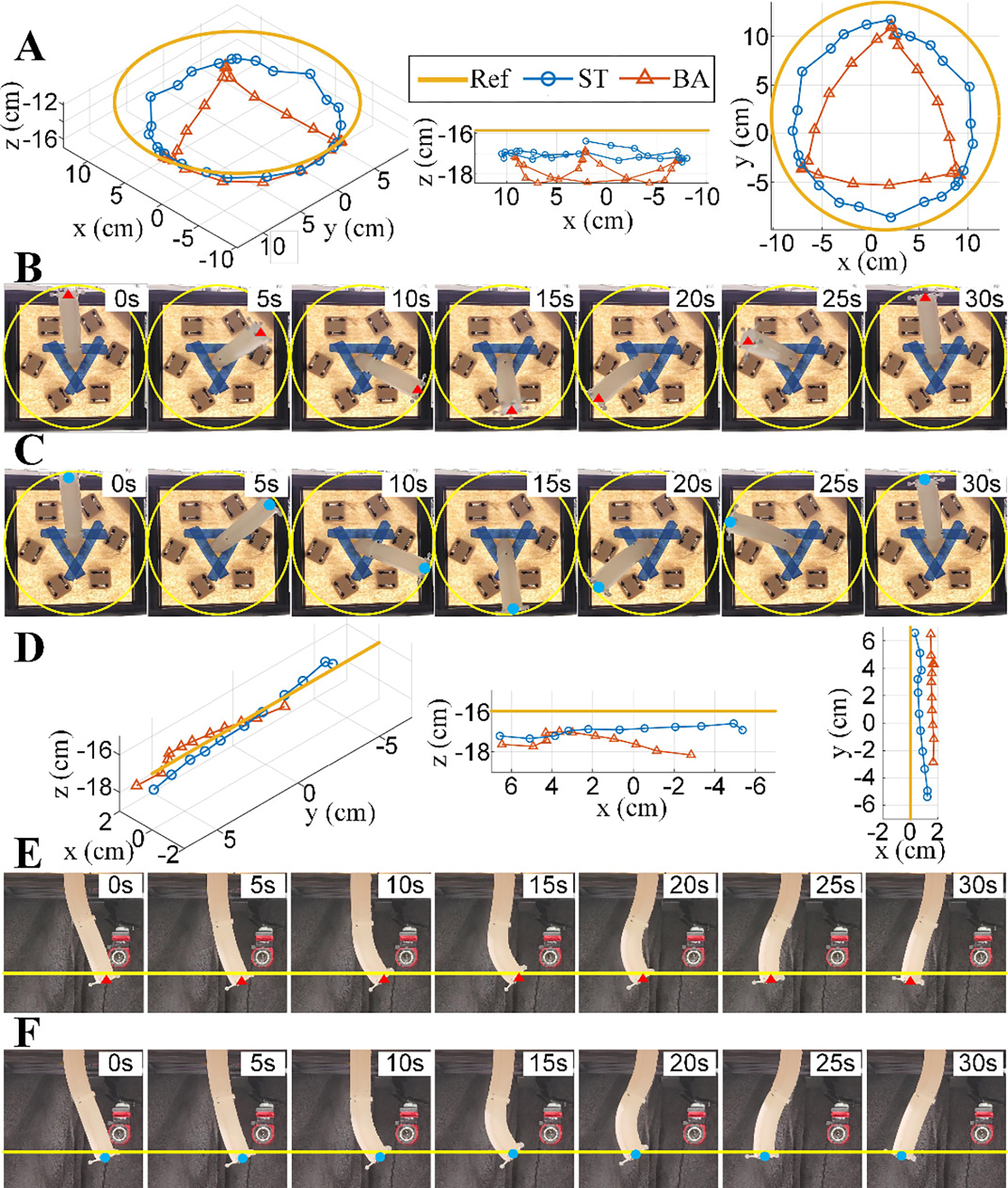
(A). Trajectories of the end position of the arm tracking a circular path by using the baseline model (BA) and the proposed static model (ST). (B). Illustration of movement and bending of the arm tracking a circular path by using BA. (C). Illustration of movement and bending of the arm tracking a circular path by using ST. (D). Trajectories of the end position of the arm tracking a straight path by using BA and ST. (E). Illustration of movement and bending of the arm tracking a straight path by using BA. (F). Illustration of movement and bending of the arm tracking a straight path by using ST. In (B), (C), (E), and (F), yellow curves indicate the reference trajectory and red/blue dots indicate the tip of the arm.