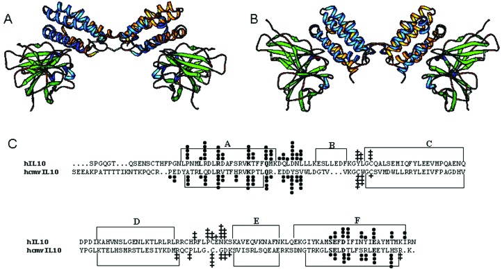
Figure 1.
Structure and sequence of the cmvIL-10/sIL-10R1 complex. (A) Ribbon diagram of the 1:2 cmvIL-10/sIL-10R1 complex viewed perpendicular to the twofold axis of cmvIL-10. (B) Ribbon diagram of 1:2 hIL-10/sIL-10R1 complex in the same orientation as A. (C) Structure-based sequence alignment of hIL-10 and cmvIL-10. α-Helices are defined by brackets and labeled. cmvIL-10 or hIL-10 residues that bury surface into sIL-10R1 or into their respective dimer interfaces are marked with circles and crosses, respectively. The amount of buried surface area is denoted by different numbers of circles or crosses with 1 > 5 Å2, 2 > 10 Å2 < 35 Å2, 3 > 35 Å2 < 60 Å2, 4 > 60 Å2 < 85 Å2, and 5 > 85 Å2.

