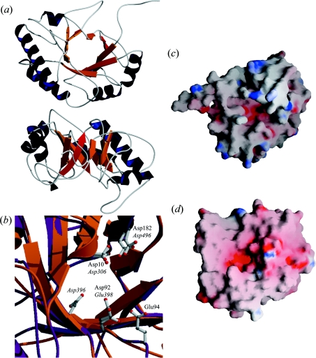
Figure 2. Structural model of the catalytic module of LytC.
(a) Views from the N-terminal side of the barrel (top) and the region lacking α6–α8 helices (bottom). Helices and strands are coloured dark blue and orange respectively; antiparallel β8 is highlighted in red. (b) Superposition of the catalytic cavities of LytC (orange) and Cpl-1 (purple). Catalytic residues of Cpl-1 and putative catalytic residues in LytC are in ball-and-stick representation (C atoms, grey; N atoms, blue; O atoms, red). Labels indicate their position in the sequence of Cpl-1 (roman) and LytC (italic). (c and d) Surface electrostatic potentials of LytC and Cpl-1 respectively. Negatively charged regions are coloured red, and positive regions are blue.

