
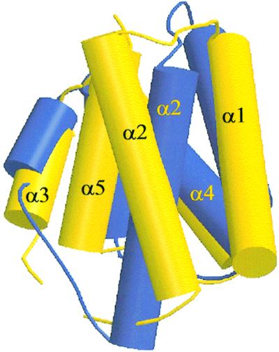
Fig. 6. Structure superposition of PRD1 (yellow) and PRD2 (blue). Helices are represented as solid cylinders. All Cα positions were used in the fit of the two modules. The helices α3, α4 and α5 of PRD1 and PRD2 superpose relatively well. The α1 helix in PRD2 is shifted over 5 Å along the helical axis in the N-terminal direction compared with α1 in PRD1, while α2 has pivoted by 30° around the centre of the helix compared with α2 in PRD2.