Abstract
To improve the dynamic response of the linear induction machine (LIM) over its complete speed range, this paper introduces a finite state-model predictive voltage control (FS-MPVC) based on terminal sliding mode control (TSMC). First, the TSMC for the speed loop is designed to attain high tracking capability and faster transient response. Second, in terms of the intricate balancing coefficient tuning difficulty and several computation steps of the conventional finite state-model predictive thrust control method, the control objectives are transformed to the primary voltage based on the FS-MPVC method. Furthermore, the TSMC-MPVC is fully studied in detail, covering its design and implementation steps. Ultimately, a 3 kW LIM has undergone comprehensive simulation evaluations by the presented TSMC-MPVC through comparing with the conventional methods at various speeds and loads to verify the effectiveness and viability of the proposed method.
Keywords: Linear induction machine (LIM), Finite state-model predictive voltage control (FS-MPVC), Terminal sliding mode control (TSMC)
Subject terms: Engineering, Electrical and electronic engineering
Introduction
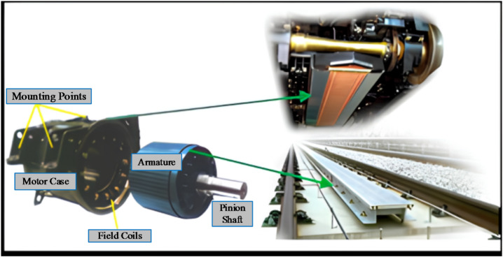
The linear induction motors (LIMs) are promising option for different industrial applications, particularly light railway1,2, due to its ability to get much stronger hill climbing ability, thrust directly capability, smaller turning radius, low maintenance cost, and fast acceleration/deceleration, reduced noise, etc3. The LIMs have evolved from the rotary induction motors (RIMs) by adopting the cutting of the main parts, then slicing them open and rolled flat, as shown in Fig. 1. Thus far, in different countries they have been implemented for commercial metro lines systems4–6.
Fig. 1.
The LIM is represented by RIM.
Due to the open magnetic circuit, LIM suffers from the problem of longitudinal end effect, in turn, leads to variation in mutual inductance especially with high speed. Such a phenomenon, LIMs have a negative impact on the whole dynamic drive operation, and the LIMs have lower efficiency than the RIMs7–10. Generally, because of the primary and secondary of LIMs have high nonlinear characteristics and coupling, the driving performance of conventional control techniques is more challenging on LIMs than on RIMs11. There are two main control structures available for the drive systems: field-oriented control, due to the changes in LIM driving system parameters is slower and many parameters are needed and direct thrust control, it has higher ripples for both flux and thrust also has variable switching frequency that caused by the thrust and flux comparator12–14. Because of its reliable performance, the field control method is frequently used in RIMs that are applied to traction drive systems. When the rotor flux (d-axis current) stays constant, the traction control drive systems under constant torque will be obtained. The slip frequency (q-axis current), if the aforementioned criterion is met, will proportionately determine the motor torque.
Therefore, a number of research studies have proposed that the traditional direct thrust control (DTC) of the LIM can be used. Three PI regulators had to be properly adjusted for thrust, speed, and flux loop, respectively, in order to use the recommended methods15–17.
Thus, in LIM drive systems, increasing focus has been placed on model predictive control (MPC) techniques to address the problems with the conventional DTC and field control methods. Where the advantages of MPC include easier to handle various constraints, online optimization, rapid dynamic response, easy to implement, and so on18. The MPC is categorized into two substantial systems, one is finite state-MPC (FS-MPC) and Continuous state-MPC (CS-MPC)19. Once more, the FS-MPC is separated into two categories based on the evaluated objective function: (a) FS-Predictive Thrust/Torque Control (FS-PTC), and (b) FS-Predictive Current Control (FS-PCC)20.
Generally, the FS-PTC requires to predict the thrust and flux linkage, in which the voltage vector that minimizes the error between the controlled predicted variables with their reference values is selected as the optimal one for applying on the voltage source inverter in the next sampling time. This process needs a balancing coefficient to preference the priorities of the control objectives based on the cost function design21.
Undoubtedly, FS-MPC exhibits greater efficiency than the traditional DTC method due to the online evaluation based on a cost function instead of offline switching table and hysteresis comparators. In spite of these abovementioned advantages of the MPC, it has higher computation burden, particularly the tuning of the weighting factors for the FS-PTC approach. Since the FS-PTC needs the balancing coefficient to harmony the control variables of the cost function, the weighting factorless cost functions are proposed in22–24 by unifying the cost function dimensions i.e., based on primary flux vector only. However, the proposed method in25 the flux item is altered by the thrust item. Because of the items that need to be predicted is reduced, fewer prediction processes are attained, which will improve the computation burden. Additionally, the consuming time in tuning process can be reduced by removing any balancing factor. A brief comparison between different control techniques is summarized in Table 1.
Table 1.
Summarized comparison between virous control strategies.
| Control Strategy | Advantages | Disadvantages |
|---|---|---|
| FOC |
Lower thrust ripple Lower flux ripple |
Slow response Depends on machine parameters Need more coordinate transformations |
| DTC |
Fast response Needs only the primary resistance No need for coordinate transformations |
Higher thrust ripple Higher flux ripple Variable switching frequency |
| FS-PTC |
Fast response Lower thrust ripple Lower flux ripple |
Depends on the machine parameters |
A high-performance LIM drive system can be realized by replacing the PI controller with a robust control approach. Conversely, a sliding mode controller (SMC) is utilized in the drive system due to its robustness, straightforward implementation, and strong adaptability to load variations26. Sliding mode control (SMC) is a promising option for transportation applications, offering adaptability to load variations, robustness, insensitivity to unknown parameters and disturbances, and ease of practical implementation. For permanent magnet direct drive systems, a fuzzy sliding mode controller (Fuzzy-SMC) with a smooth switching function is proposed to enhance speed control stability under parameter uncertainties and disturbances. Simulation comparisons with PI and conventional SMC show that Fuzzy-SMC achieves smaller overshoot and superior robustness27. A comparative study of first- and second-order sliding mode control for squirrel-cage induction motors using a two-level inverter demonstrates the robustness of SMC in handling uncertainties and disturbances. Results show that FOSMC with a hyperbolic tangent function reduces response time, while SOSMC enhances tracking accuracy and minimizes chattering with fewer control loops28.
Therefore, in this paper, the balancing coefficient is removed by adopted the αβ-axes primary voltage as a direct control variable in the presented cost function, which is known as FS-PVC. Furthermore, to strengthen the robustness of the PVC method in LIM, a robust terminal sliding mode control (TSMC) is adopted to achieve faster transient response and high tracking ability with lower thrust ripple for the LIM.
The rest of this paper is organized as follows. The dynamic modeling of the LIM drive system is presented in Section II. The FS-PVC method is fully designed and presented in Section III. The speed controller based on TSMC under the FS-PVC strategy is designed for the LIM, which is represented in section IV. Comprehensive simulation results are presented in Sections V, which are fully established that the proposed TSMC based FS-PVC can have stronger anti-disturbance ability, faster convergence speed, smaller thrust and flux ripples, and so on. Finally, conclusions have been drawn.
Modeling of the LIM
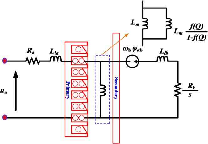
Figure 2 illustrates an equivalent circuit of the LIM drive system in the stationary reference frame αβ-axis to design its model29. According to the aforementioned equivalent circuit, the model of the LIM in stationary frame can be expressed as below:
Fig. 2.
The equivalent circuit of the LIM under αβ-axis frame.
The voltage equations on the αβ-axes can be expressed as
| 1 |
| 2 |
where a and b refer the primary and secondary parameters of the LIM in the stationary αβ-axes for the voltage (u), resistance (R), current (i), and flux (ψ), respectively. Additionally, the slip angular velocity ωslip is defined as the difference between the simultaneous speed ωa and rotating speed ωb.
The flux equations on the αβ-axes are expressed as
| 3 |
| 4 |
where La, and Lb, are the primary, secondary leakage inductance parameters; Lmeq the equivalent magnetizing inductance modified by the factor f(Q)30. Then, the electromagnetic thrust is expressed as
| 5 |
where τ is denotes as the primary polar length. Then, can be given the mechanical equation by
| 6 |
where J is the compensate coefficient; G is the mass; H viscous friction coefficient; vb is the speed of the LIM; and Fl is the load thrust. The modified magnetizing inductance with correction of the longitudinal edge effects for the LIM, can be updated by the coefficient f(Q), as demonstrated by31.
| 7 |
| 8 |
where  and
and  are the primary and secondary inductances based on the modified magnetizing inductance. The corrected magnetizing inductance is defined as
| 9 |
where Lm is the magnetizing inductance before consideration of the end effect.
Finite state-model predictive control for LIM drive system
In this section, the finite state-model predictive control is designed for the FS predictive based on voltage control (FS-PVC).
Finite state model predictive based on voltage control
The thrust and primary flux terms, which have different units, were included in the traditional cost function of the FS-PTC that is being provided. Various dimensions present certain difficulties for thrust and flux error optimization. The predictive voltage control (PVC) approach uses primary voltage exclusively for prediction, minimizing thrust and flux ripples and cutting down on computation time. The cost function in the PVC is applied without the use of a balancing coefficient based on the primary voltage. The thrust and primary flux reference values are utilized to derive the voltage reference using the method described, as shown by
| 10 |
where  is the primary voltage’s relative function and
  is the primary voltage reference. The dead-beat method is used to calculate the desired primary voltage in the next instant
  which uses the thrust and flux references rather than their predicted values, as expressed by
| 11 |
The following stages serve as a brief summary of how the FS-PVC approach is implemented.
Estimations of primary flux
 as well as secondary flux
  , are elaborated by.
| 12 |
| 13 |
Computation the primary voltage reference
 .
.
For the next control period, the predicted thrust is set to its reference value based on the deadbeat control approach. Likewise, the reference value determines the predicted primary flux value, as shown below
| 14 |
| 15 |
The desired primary flux angle  of the next period can be computed using
| 16 |
| 17 |
| 18 |
The secondary flux angle  is added to the calculate angle as obtained from the thrust equation in the rotating frame. So, the primary flux reference
  can be calculated by
| 19 |
Both the predicted primary flux and the predicted flux angle can eventually obtain the desired αβ-axis voltage reference in the next control period, as determined by
| 20 |
Optimization on the cost function.
The error between the  output VV of the inverter states and the primary reference voltage on the αβ-axis makes up the proposed cost function. The ideal choice for the next sample period will be the VV that minimizes the cost function’s (J) value (i.e., the least distance between the reference voltage and the candidates), where only the αβ-axis primary voltage tracking error between the predicted and their reference values are involved, as follows:
| 21 |
Unlike the traditional prediction model22, which requires seven iterations during each control period, the proposed method relies on a single prediction using the deadbeat control concept. This results in a significantly shorter computation time. Figure 3 shows the flow chart of the FS-MPVC for LIM drive system.
Fig. 3.

The flow chart of the FS-MPVC strategy.
Proposed terminal sliding mode control based speed control with FS-MPVC for the LIM
The LIM’s speed control system is designed using terminal sliding mode control within the FS-PVC framework, according to the speed control loop for the LIM.
Speed control utilizing sliding trajectory
The LIM speed error has been selected as the sliding mode state variable for the speed loop. The goal of the LIM speed controller is to make the LIM speed vb follow the vb* reference speed. This objective can be achieved by the creation of the control law. To illustrate the discrepancy between the preset linear speed vb* and its actual value vb, the tracking error  and its derivation
  are provided as follows.
| 22 |
It is possible to define the terminal sliding mode trajectory as
| 23 |
where k is a constant gain and  .
.
The SMC design heavily relies on the reaching law, which is depicted as
| 24 |
where the constant parameters of the reaching law are denoted by the letters k1 and k2. The sliding mode state will be reached on the sliding surface with stability when the  condition is met9.
Speed regulation based on final control law
Developing a controller for the speed loop will allow the LIM’s actual signal to follow its reference value. As a result, the TSMC’s speed control loop is meticulously designed so that the actual speed stays relatively close to the LIM speed’s preset value. Therefore, using the TSMC approach and the mechanical Eq. (6), the speed control loop can be modified as indicated by
| 25 |
where Bn=-Dn=(JG)−1, and An=-H/G, are different factors under the nominal working conditions. Moreover, G represents mass, and H is the viscous coefficient of LIM. Under external load disturbance, the LIM’s mechanical dynamics can be rewritten as
| 26 |
| 27 |
In the meanwhile, the  can be written as
| 28 |
By replacing (27) into the derivative of speed error ( ), it will get
| 29 |
The sliding mode surface and reaching law are defined in (23) and (24), separately. By combining (23), (24), and (29), the thrust reference based on the TSMC can be expressed as
 |
30 |
The sliding mode state will arrive at the recommended sliding trajectory in a finite amount of time with zero error since the control law’s coefficients, k1, k2, and k, were carefully chosen. The use of the discontinuous sign function, sgn(s), often leads to significant chattering and undesirable system behavior. To mitigate this issue, the continuous saturation function, sat(s), is employed as a replacement. This function effectively reduces chattering and can be expressed as follows
| 31 |
Where  is a small positive constant. The LIM system based on the TSMC method for is presented in Fig. 4. Moreover, the final block diagram of the TSMC with FS-MPVC is depicted in Fig. 5.
Fig. 4.
The reference thrust of LIM speed control based TSMC method.
Fig. 5.
The TSMC based FS-MPVC for the LIM drive system.
Simulation and analysis
To verify that the proposed TSMC based on the FS-PVC method is superior and effective. The linear speed, thrust, primary flux and primary current of the LIM under TSMC-MPVC, CSMC-MPVC and PI-MPVC control methods are compared through simulation analyses under three operating scenarios. The machine and the simulation parameters are defined in Tables 2 and 3, respectively.
Table 2.
Detailed parameters of the AIM.
| Quantity | Symbol | Value | Unit |
|---|---|---|---|
| Rated thrust | F N | 270 | N |
| Rated speed | v N | 11 | m/s |
| Rated current | I N | 22 | A |
| Rated voltage | v | 180 | V |
| Primary length | l s | 1.3087 | m |
| Primary leakage inductance | L la | 0.009 | H |
| Primary resistance | R a | 1.06 | Ω |
| Secondary resistance | R b | 2.4 | Ω |
| Pole pitch | τ | 0.1485 | m |
Table 3.
The control methods parameters.
| Name | Value |
|---|---|
| PI gains for PI-MPVC | 300 and 0.3 |
| Switching gains for the TSMC-MPVC |

|
Case 1: Start-up response
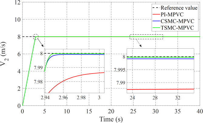
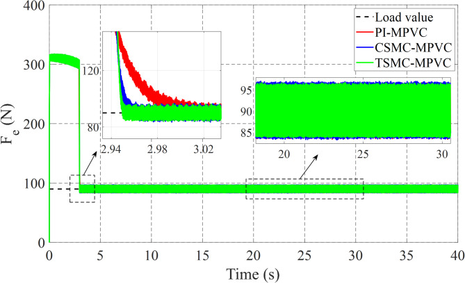
The performance of three test methods for this case has been evaluated under specific working conditions. In the assessment, constant load and speed responses were examined on the LIM drive system. The speed response was varied from 0 to 8 m/s with a 90 N load maintained for the entire simulation duration across TSMC-MPVC, CSMC-MPVC, and PI-MPVC methods individually. Upon analysis, it is evident from Fig. 6 that the speed response achieved with TSMC-MPVC exhibits superior tracking capability with faster convergence compared to CSMC-MPVC and PI-MPVC methods. This suggests the efficacy of the TSMC-MPVC approach over its counterparts in achieving desired speed responses efficiently. Furthermore, Fig. 7 illustrates the thrust results of the LIM drive system. It is noteworthy that the thrust attained through TSMC-MPVC method exhibits quicker initiation towards reaching steady-state operating conditions compared to CSMC-MPVC and PI-MPVC methods, respectively. This enhancement underscores the superior performance of the TSMC-MPVC method in terms of both speed response tracking and thrust attainment, indicating its effectiveness in practical applications over the other evaluated methods. Moreover, Fig. 7 reveals that the proposed TSMC-MPVC method exhibits the smallest thrust ripple value as well as reaches steady-state performance more rapidly compared to the CSMC-MPVC and PI-MPVC control methods. This reduction in thrust ripple signifies enhanced stability and smoother operation, highlighting the superiority of the TSMC-MPVC approach. Additionally, Fig. 8 presents the primary flux results for all control techniques, indicating nearly identical values during the specified working conditions. This suggests that all methods are comparable in terms of primary flux performance under these conditions. Finally, Fig. 9 depicts the phase current during the starting performance phase for TSMC-MPVC, CSMC-MPVC, and PI-MPVC methods. It is evident from Fig. 9 that the starting current time for TSMC-MPVC is significantly lower than that of CSMC-MPVC and PI-MPVC methods, respectively. This reduction in starting current time further emphasizes the efficiency and responsiveness of the TSMC-MPVC method, making it a favorable choice for applications requiring quick and precise control responses.
Fig. 6.
Speed response of all control strategies under starting process.
Fig. 7.
Thrust response of all control strategies under starting process.
Fig. 8.
Primary flux of all control strategies response under starting process.
Fig. 9.
Input Phase-A response of all control strategies under starting process.
Case 2: speed change response
The linear speed change response on the LIM drive system has been fully checked in this subsection under TSMC-MPVC, CSMC-MPVC, and PI-MPVC separately. The working conditions of three test methods are set as follows: A constant load of 180 N on LIM is applied during the total simulation time. The reference speed 6 m/s is set for 0–10 s. During 10–20 s, set the reference speed 9 m/s. During 20–30 s, set the reference speed 7 m/s. During 30–40 s, set the reference speed 11 m/s has been depicted in Fig. 10. It can be observed adopting this working scenario that the behavior of the speed with TSMC-MPVC has a short period for reaching its reference as well as a smaller tracking error than that of CSMC-MPVC and PI-MPVC. Moreover, Fig. 11 shows the thrust response under this working scenario for TSMC-MPVC, CSMC-MPVC, and PI-MPVC, respectively. Compared with the PI-MPVC and CSMC-MPVC, TSMC-MPVC has a faster response to reach steady-state behaviors.
Fig. 10.
Speed response under variable speed.
Fig. 11.
Thurst response under variable speed.
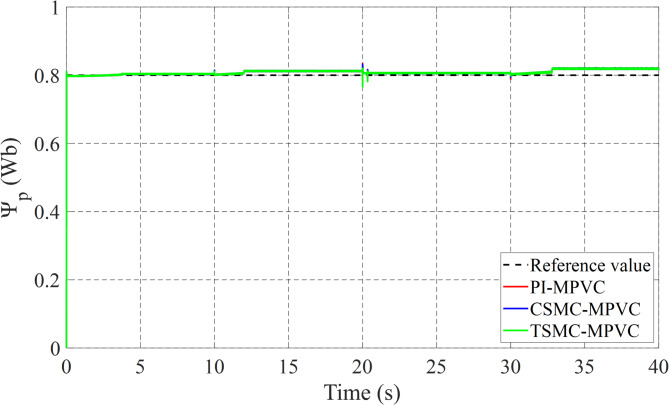
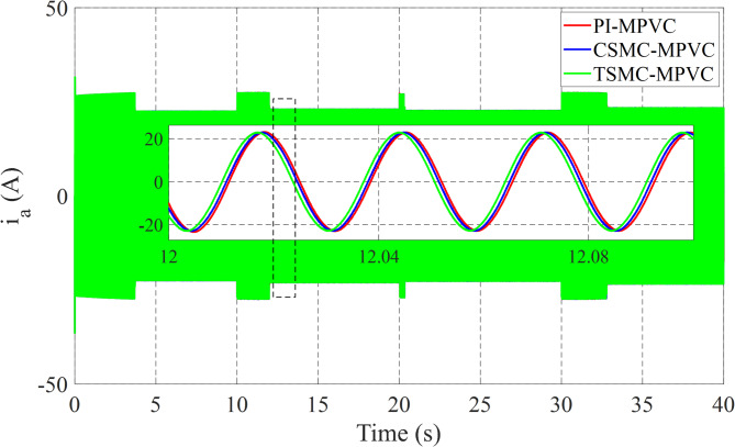
Figure 12 shows the primary flux result for all control techniques under this working condition. It can be noted that the actual values are nearly the same during this working case. Figure 13 shows the results of the input Phase-A current with TSMC-MPVC, CSMC-MPVC, and PI-MPVC. It can be seen from this result that the current reaches a set rated value for a short period under the TSMC-MPCC than that of other control methods.
Fig. 12.
Primary flux-linkage response under variable speed.
Fig. 13.
Input Phase-A current response under variable speed.
Case 3: load change response
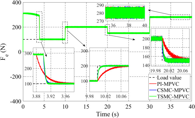
The load change dynamic response test under constant speed is fully studied in this subsection under TSMC-MPVC, CSMC-MPVC, and PI-MPVC separately for the LIM drive system. Firstly, the LIM drive has been started when machines reach the steady state condition, hence a 100 N load has been added and the load has been increased by 100% from 100 N to 200 N during 10–20 s with a reference speed set as 10 m/s. Again, the load has been reduced to the value, 150 N during 20-30s. Afterwards, the load has been increased from 150 N to 280 N during 30–40 s. Figure 14 shows the thrust performance under the three control methods thorough this simulation scenario. From this figure, it can be observed that the response has faster convergence with TSMC-MPVC than those with CSMC-MPVC and PI-MPVC, individually. This further confirms the superiority of the proposed TSMC-MPVC method. The speed response for different control methods is compared and presented in Fig. 15. It is depicted that the speed response with TSMC-MPVC has a short period for reaching its reference value as well as a smaller tracking error than that of CSMC-MPVC and PI-MPVC, which proves the effectively the proposed TSMC-MPVC method. The proposed method responds more quickly response, because the TSMC can enter sliding mode states very fast when it is near or far from the designed surface with robust anti-disturbances. Similar to the starting case, the primary flux linkage performance when the load changed for TSMC-MPVC, CSMC-MPVC, and PI-MPVC is shown in Fig. 16. It can be concluded from this image that the actual values are nearly the same during this working case for different control methods. Moreover, it is demonstrated that the Phase-A current is effectively changed in different working loads for three control methods with a short period for reaching a set rated value under the proposed TSMC-MPVC method as presented in Fig. 17.
Fig. 14.
Thrust response under variable load.
Fig. 15.
Speed response under variable load.
Fig. 16.
Primary flux under variable load.
Fig. 17.
Input Phase-A current under variable load.
Conclusions
To enhance the dynamic response of the LIM drive system, this study introduces a FS-MPVC method based on TSMC. The proposed MPVC simplifies the tuning complexity of the balancing coefficient by constructing its cost function based on the primary voltage. Additionally, TSMC is fully integrated with a speed loop using the MPVC approach. The three control methods, proposed TSMC-MPVC, CSMC-MPVC and PI-MPVC were compared under various operating conditions, including startup, load changes, and speed alteration. Overall, the simulation results demonstrate that the TSMC-MPVC method outperforms the other methods in terms of effectiveness and features. Notably, TSMC-MPVC reduces thrust and flux ripples, thereby effectively minimizing the LIM’s noise and vibration. The proposed scheme should be validated through experimental tests in subsequent work.
Acknowledgements
The authors also acknowledge technical support received from the Renewable Energy Lab at Prince Sultan University, Riyadh, Saudi Arabia.
Author contributions
S.A. writing, reviewing, Methodology, Software; F. F. Formal analysis, overall editing; M. M. Formal analysis, Software, Writing & editing; M.F. Formal analysis, editing the manuscript; original draft, Editing, Reviewing; D.A. Editing, Reviewing of the response letter; M.A. Investigation, Validation. All authors reviewed the manuscript.
Funding
Open access funding provided by The Science, Technology & Innovation Funding Authority (STDF) in cooperation with The Egyptian Knowledge Bank (EKB).
Data availability
All data generated or analysed during this study are included in this published article.
Declarations
Competing interests
The authors declare no competing interests.
Footnotes
Publisher’s note
Springer Nature remains neutral with regard to jurisdictional claims in published maps and institutional affiliations.
References
- 1.Boldea, I., Tutelea, L., Xu, W. & Pucci, M. Linear electric machines, drives, and maglevs: an overview. IEEE Trans. Ind. Electron.65(9), 7504–7515 (2018). [Google Scholar]
- 2.Xu, W. et al. Discrete space vector modulation-based MPCC with inductance identification for thrust ripple suppression in linear induction machine. IEEE Trans. Power Electron.39(10), 12883–12893 (2024). [Google Scholar]
- 3.Xu, W., Zhu, J., Guo, Y., Tan, L. & Wang, S. Analysis on performance of linear induction motor basing on winding function method. in Proc. IEEE Conf. Ind. Electron. Appl 3639–3642 (2009).
- 4.Xu, W., Zhu, J. G., Member, S. & Zhang, Y. Equivalent circuits for single-sided linear induction motors. IEEE Trans. Ind. Appl.46(6), 2410–2423 (2010). [Google Scholar]
- 5.Boldea, I. Linear Electric Machines Drives and Maglevs Handbook (CRC Press, 2013).
- 6.Hamad, S. A. et al. Model predictive voltage control for linear induction machine without weighting factor. in Proc. 13th Inter. Sym. on Linear Drives for Ind. Appl. (LDIA), Wuhan, China 1–6 (2021).
- 7.Alonge, F., Cirrincione, M., Pucci, M. & Sferlazza, A. Input-output feedback linearization control with on-line MRAS-based inductor resistance Estimation of linear induction motors including the dynamic end effects. IEEE Trans. Ind. Appl.52(1), 254–266 (2016). [Google Scholar]
- 8.Karimi, H., Vaez-zadeh, S. & Salmasi, F. R. Combined vector and direct thrust control of linear induction motors with end effect compensation. IEEE Trans. Energy Convers.31(1), 196–205 (2016). [Google Scholar]
- 9.Hamad, S. A. et al. Improved full order sliding mode based on model predictive flux control for LIM applied to urban transit. IEEE Trans. Transp. Electrific. 11(1), 2556–2570 (2025). [Google Scholar]
- 10.Lv, G., Zeng, D., Zhou, T. & Liu, Z. Investigation of forces and secondary losses in linear induction motor with the solid and laminated back iron secondary for metro. IEEE Trans. Ind. Electron.64(6), 4382–4390 (2017). [Google Scholar]
- 11.Cheema, M. A. M., Fletcher, J. E., Xiao, D. & Rahman, M. F. A direct thrust control scheme for linear permanent magnet synchronous motor based on online duty ratio control. IEEE Trans. Power Electron.31(6), 4416–4428 (2016). [Google Scholar]
- 12.Jiang, Y., Xu, W. & Ye, C. Composite field-oriented control for linear induction motor based super-twisting sliding mode observers. in Proc. IEEE Conf. Electromagn. Field Comput. (CEFC), Miami, FL, USA 1–6 (2016).
- 13.Ke Wang, Q. G., Li, Y. & Shi, L. A novel switching scheme for direct thrust control of LIM with reduction of thrust ripple. in Proc. Int. Con. Elect. Mach. Syst 1491–1494 (2010).
- 14.Abdelfatah, N. & Brahim, G. A novel lithium ion battery autonomous strategy improvement based on SVM-DTC for urban electric vehicle under several speeds tests. Majlesi J. Electr. Eng.5(4), 40–45 (2011). [Google Scholar]
- 15.Wang, F., Li, S., Mei, X., Xie, W. & Rodríguez, J. Model-based predictive direct control strategies for electrical drives: an experimental evaluation of PTC and PCC methods. IEEE Trans. Ind. Informat. 11(3), 671–681 (2015). [Google Scholar]
- 16.Xie, W. et al. Finite-control-set model predictive torque control with a deadbeat solution for PMSM drives. IEEE Trans. Ind. Electron.62(9), 5402–5410 (2015). [Google Scholar]
- 17.Ahmed, A. A., Koh, B. K. & Lee, Y. A comparison of finite control set and continuous control set model predictive control schemes for speed control of induction motors. IEEE Trans. Ind. Informat. 14(4), 1334–1346 (2018). [Google Scholar]
- 18.Ali, M. M. et al. Improved drive performance of linear induction machine based on direct thrust control and sliding mode control with extended state observer applied for linear metro. in Proc. 13th Inter. Sym. on Linear Drives for Ind. Appl. (LDIA), Wuhan, China 1–6 (2021).
- 19.Mo, R. et al. Low-complexity virtual-vector-based FCS-MPC with unaffected neutral-point voltage for three-phase T-type inverters. IEEE J. Emerg. Sel. Top. Power Electron.12(2), 1683–1693 (2024). [Google Scholar]
- 20.Hamad, S. A. et al. Improved MPCC with duty cycle modulation strategy for linear induction machines based on linear metro. IEEE International Conference on Predictive Control of Electrical Drives and Power Electronics (PRECEDE), China 35–40 (2021).
- 21.Zhang, Y., Yang, H. & Xia, B. Model predictive torque control of induction motor drives with reduced torque ripple. IET Elect. Power Appl.9(9), 595–604 (2015). [Google Scholar]
- 22.Xu, W. et al. Thrust ripple suppression for linear induction machines based on improved finite control set-model predictive voltage control. IEEE Trans. Ind. Appl.58(6), 7263–7274 (2022). [Google Scholar]
- 23.Zhang, Y., Jin, J. & Huang, L. Model-free predictive current control of PMSM drives based on extended state observer using ultralocal model. IEEE Trans. Ind. Electron.68(2), 993–1003 (2021). [Google Scholar]
- 24.Hamad, S. A. & Ghalib, M. A. Fuzzy MPPT operation-based model predictive flux control for linear induction motors. Int. J. Hydrog. 50(Part B), 1035–1044 (2024).
- 25.Wang, F. et al. Parallel predictive torque control for induction machines without weighting factors. IEEE Trans. Power Electron.35(2), 1779–1788 (2020). [Google Scholar]
- 26.Ali, M., Cheema, M., Fletcher, J. E., Farshadnia, M. & Rahman, M. F. Sliding mode based combined speed and direct thrust force control of linear permanent magnet synchronous motors with first-order plus integral sliding condition. IEEE Trans. Power Electron.34(3), 2526–2538 (2019). [Google Scholar]
- 27.Qiao, Y. & Wang, K. Fuzzy sliding mode speed control strategy of permanent magnet motor under variable load condition. Int. J. Dynam Control. 12, 1616–1625 (2024). [Google Scholar]
- 28.Halimi, H. et al. High-order sliding mode control with hyperbolic evaluation function for improving performances of a squirrel-cage induction motor fed by a two-level inverter. Int. J. Dynam Control. 12, 2929–2943 (2024). [Google Scholar]
- 29.Shadmand, M. B., Jain, S. & Balog, R. S. Autotuning technique for the cost function weight factors in model predictive control for power electronic interfaces. IEEE J. Emerg. Sel. Top. Power Electron.7(2), 1408–1420 (2019). [Google Scholar]
- 30.Duncan, J. Linear induction motor equivalent-circuit model. Proc. Inst. Elect. Eng.130(1), 51–57 (1983). [Google Scholar]
- 31.Bukhari, S. A., Xu, W., Elmorshedy, M. F., Junejo, A. K. & Hamad, S. A. Upgraded Limited-Step Predictive Current Control Strategy for Linear Induction Machine based on Linear Metro. in Proc. 13th Inter. Sym. on Linear Drives for Ind. Appl. (LDIA), Wuhan, China 1–6 (2021).
Associated Data
This section collects any data citations, data availability statements, or supplementary materials included in this article.
Data Availability Statement
All data generated or analysed during this study are included in this published article.


