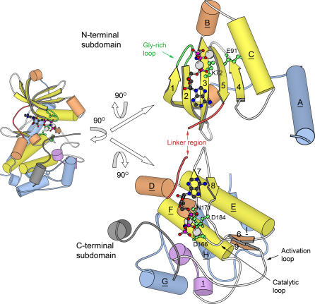
Figure 1. Two Views of the Structure of PKA [70].
The structure consists of two subdomains: a small, primarily β-sheet N-terminal subdomain, and a larger, primarily helical C-terminal subdomain. ATP and metal ions are bound in the cleft between the two subdomains. The small left-side view depicts PKA in the “standard” orientation used by the authors when the structure was initially solved [12], and in many subsequent publications. The larger view on the right side depicts PKA in an “open-book” format that makes structural features in the two subdomains easier to compare between families. The open-book view is achieved by rotating the standard view 90° about the vertical axis, then splitting the two subdomains at the linker region and rotating each 90° in opposite directions about the horizontal axis. Helical secondary structures (both α-helices and 3–10 helices) are depicted as cylinders, and β-strands are depicted as arrows. Elements are labeled according to the standard conventions for PKA. Some secondary structure (particularly 3–10 helices) is not labeled in the standard PKA convention, and so is unlabeled here. One structure (Helix 1) was named by us (see text). Underlined labels belong to helical structures; non-underlined labels belong to β-strands. Secondary structure elements are colored according to their conservation status in the overall superfamily as follows: yellow, elements are part of the “universal core” seen in all kinases in the superfamily; orange, elements are present in more than two, but not all, of the kinases in the superfamily; purple, elements seen only in this family, but inserted within in the portion of the chain forming the universal core; blue, elements seen only in this family, and connected to the N- or C-terminal ends of the universal core. A bound pseudosubstrate inhibitor (PKI) is present in the structure [12], and depicted in gray. This inhibitor likely describes the binding location of actual substrates of PKA. The bound ATP molecule is rendered as a ball-and-stick model, while the bound Mg ions are rendered as gray spheres. The ATP and Mg ions are duplicated in mirror image and shown interacting with both the N- and C- terminal subdomains in the open-book rendering. The most critical and highly conserved residues in PKA (and the broader superfamily) are shown as ball-and-stick models in green, and labeled according to the standard PKA numbering scheme. In addition, the glycine-rich loop is also depicted in green, though individual glycine residues are not shown. The loop that forms the linker region between the subdomains is depicted in red. Other loops within the universal core are shown in white, except for loops linking purple regions (which are shown in purple), and loops outside of the universal core (shown in blue). Key loops described extensively in the text are labeled. For increased clarity, residues 300–350 have been removed from the C-terminus of PKA. This loop region is unique to PKA, and would have been colored blue if present in the figure. Molecular renderings in this figure were created with MOLSCRIPT [90].

