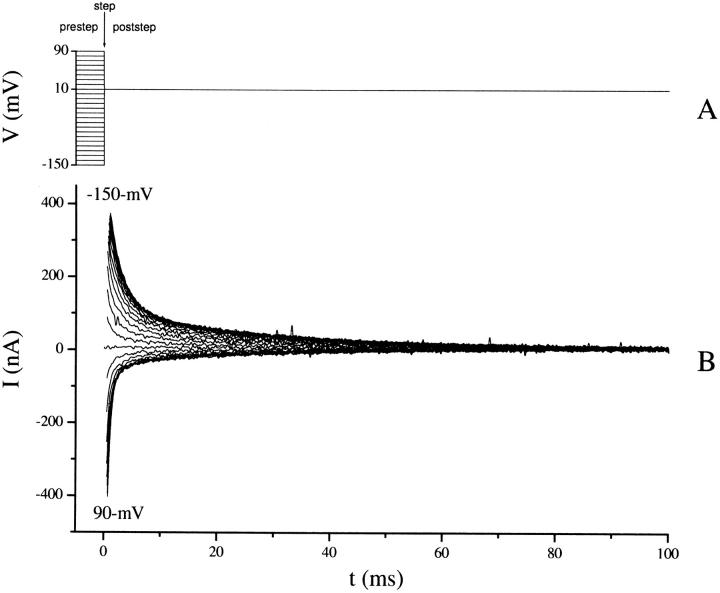
FIGURE 2.
SGLT1 transient currents. (A) Overlay of 25 traces showing membrane potentials applied to produce currents in B. Prestep potentials were applied for 100 ms before the step at t = 0 to allow the system to stabilize (not shown). A voltage step occurs at t = 0. Prestep potentials, defined as the membrane potential for t < 0, range from −150 to 90 mV in 10-mV steps. The poststep potential, membrane potential for t > 0, is 10 mV for all traces. (B) Set of 25 traces used to characterize the transient response of SGLT1 for a 10-mV poststep potential. Positive currents are generated from prestep potentials more hyperpolarizing than 10 mV, and negative currents from prestep potentials more depolarizing than 10 mV. Transient currents for prestep potentials of −150 and 90 mV are labeled and the intermediate potentials can be inferred from the size and sign of the transients. Currents before stabilization of the clamp have been removed.

