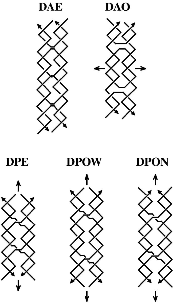
FIGURE 1.

Schematic drawings of the five different structural arrangements of double crossover structures. The structures shown are named by the acronym describing their basic characteristics. All names begin with “D” for double crossover. The second character refers to the relative orientations of their two double helical domains, “A” for antiparallel and “P” for parallel. The third character refers to the number (modulus 2) of helical half-turns between crossovers, “E” for an even number and “O” for an odd number. A fourth character is needed to describe parallel double crossover molecules with an odd number of helical half-turns between crossovers. The extra half-turn can correspond to a major (wide) groove separation designated by “W”, or an extra minor (narrow) groove separation designated by “N”. The strands are drawn as zigzag helical structures, where two consecutive, perpendicular lines correspond to a full helical turn for a strand. The arrowheads at the ends of the strands designate their 3′ ends. The structures contain implicit symmetry, which is indicated by the conventional markings: a lens-shaped figure (DAE) indicating a potential dyad perpendicular to the plane of the page, and arrows indicating a twofold axis lying in the plane of the page. Note that the dyad in the DAE molecule shown is only approximate if the central strand contains a nick, which destroys the symmetry. The DAE molecule shown contains two turns between crossovers, like the molecules used in this study. An attempt has been made to portray the differences between the major and minor grooves. Note the differences between the central portions of DPOW and DPON. Also note that the symmetry brings symmetrically related portions of backbones into apposition along the center lines in parallel molecules in these projections. The same contacts are seen to be skewed in projection for the antiparallel molecules.
