
FIGURE 3.
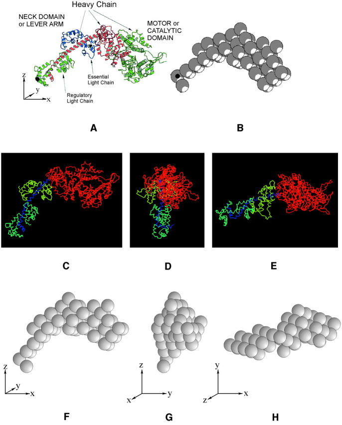
(a) The myosin head structure (Rayment et al., 1993a) as downloaded from the pdb database showing the definitions of the head orientation in terms of the x, y, and z axes and illustrating the myosin heavy chain and the two light chains (the regulatory light chain (green) and essential light chain (blue)). The long α–helical part of the heavy chain in red in the core of the regulatory light chain region provides the link between the heads and the rest of the myosin filament. The actin-binding face of the myosin head is top right and slightly facing up and out of the page. The motor or catalytic domain and the neck or lever arm are indicated. (b) Representation of a in terms of a 59-sphere model. The volume of these spheres, each of radius 8.61 Å, was chosen to express the overall mass of the myosin head, assuming constant protein density within all spheres. The black dots in a and b represent the position of the origin (0, 0, 0). (c–h) Three different views of the head in a and of its simulation in b illustrating the definition of the three head reference axes x, y, and z. These are initially set parallel to muscle reference axes X, Y, and Z. The parameters discussed in the text and in Fig. 4 refer to movements around these axes. The z axis is parallel to the muscle long axis which we call Z. If the x axis starts pointing out radially from the filament surface, this defines the filament axis X. The Y axis is orthogonal to X and Z. The head tilt (β) refers to the tilt of the head x axis around the Y-reference axis in the X-Z plane. The slew (α) refers to the rotation of the head x axis around the muscle Z axis in the X-Y plane. The rotation (θ) refers to movements around the head x axis. a shows the zero tilt position of the head, but clearly the head mass is already tilted up. The axial range of tilts was therefore set at 45° upward and 135° downward since beyond these values the heads would sterically clash with the backbone. (f–h) These show the head orientations as in c–e but for the representation of the head as a set of 59 spheres. The initial searches were carried out with the 59-sphere model (f–h). Final searches and refinements were carried out with the full pdb structure (c–e).