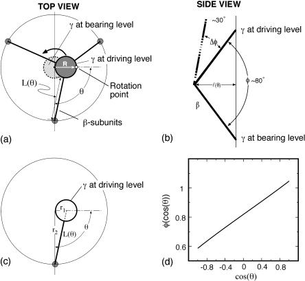
FIGURE 7.
(a) Diagram of the F1 subunit viewed from the top (membrane side) showing the three β-subunits whose bending drives the rotation of the γ-shaft. The β-subunits are shown schematically as three rods. (b) A stick model illustrating the geometric relationship between the angle, φ, of the bending of theβ-subunit and the length, L, of the HTH lever arm on β. (c) The relationship between L and θ as the power-stroke goes from 0 to π. The perspective is from the top of F1 so that the axis in the z direction is out of the figure. Each bending β-subunit, viewed from above, acts like a radial driving piston on the eccentric portion of the γ-shaft. (d) The bending angle φ is nearly a linear function of cos(θ).

