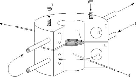
FIGURE 1.
Schematic representation of the flow dialysis cell. (1) Inlet of water from water bath at specific temperature. (2) Channels through the system for thermostatic use. (3) Upper part is fastened to the lower part to seal the contents of the lower spiral groove from the upper sample chamber. (4) The dialysis membrane (shaded) is stretched over the spiral groove and extends somewhat between the two domes. (5) Inlet of flow-through buffer (mobile phase) reaches the membrane in the middle and follows the spiral groove to the exit.

