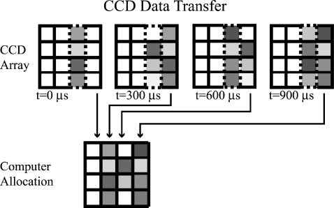
FIGURE 2.
Schematic of CCD readout mechanism. The dashed outline rectangle represents the column of the CCD array that is constantly exposed to the scattered light. The CCD array readout shift register is represented by the column of pixels at the extreme right. (Between the illuminated columns and the shift register, there may be intermediate columns but these are not shown.) The (progressive scan) camera is operated in its normal readout mode, except with the camera shutter always open. At the end of every 300-μs interval, accumulated intensity data in the illuminated column of pixels is advanced rightward column-by-column toward the shift register. At the same time, blank counts from the pixel columns to the left are shifted into the illuminated column, effectively clearing it, and data in the shift register is read into an array in the computer memory. This process continues until the shift register has read every column of the CCD array, thereby completing image acquisition for a single stage position of the sample. The final “image” as recorded in the computer consists of a time sequence (Δt = 300 μs) of 800 intensity readings at each pixel along the illuminated pixel column. The next streak-like image is acquired after the motorized microscope stage has advanced to the next position on the sample. The whole image acquisition process is complete when the stage has stepped through the entire sample.

