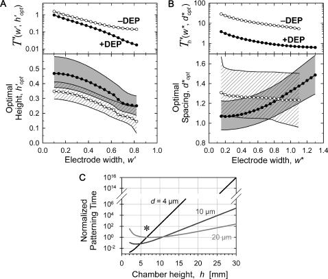
FIGURE 6.
Optimal chamber geometry parameters for −DEP (○) and +DEP (•) determined by minimizing the complete patterning time T′ or  . (A) For a constant electrode spacing (d), the optimal chamber height (h′ = h/d) decreases as electrode width (w′ = w/d) increases. (B) Similarly, for a constant chamber height (h), the optimal electrode spacing (d* = d/h) varies with electrode width (w* = w/h). Shaded or hatched regions indicate parameters resulting in efficiency within 10% of optimal. Overall, patterning time decreases with wider electrodes (top panels). (C) An example of chamber height optimization for +DEP patterning of neutrally buoyant particles within a device containing three distinct electrode geometries: d = 4, 10, and 20 μm, w′ = 0.5. Most rapid patterning for all three geometries occurs at chamber height h ∼ 7 μm (*).

