
FIGURE 1.
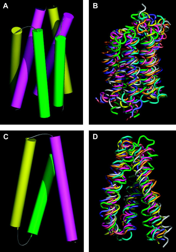
Six-helix and three-helix repeat unit in MFS proteins. (A) Helix packing derived from the density map of OxlT obtained by electron crystallography. The set of six cylinders shown corresponds to helices 7 (magenta, left), 8 (yellow, right), 9 (green, right), 10 (magenta, right), 11 (yellow, left), and 12 (green, left) of OxlT. (B) Superposition of the eight six-helix motifs from the structures of GlpT and LacY after alignment. Each six-helix unit was aligned using the C-terminal half of GlpT as a reference because it was closest to the average structure obtained from all four six-helix units as shown in Table 1. (C) Helix packing derived from the density map of OxlT obtained by electron crystallography. The set of three cylinders shown corresponds to helices 7 (magenta), 8 (yellow), and 9 (green) of OxlT. (D) Superposition of the eight three-helix motifs from the structures of GlpT and LacY after alignment. Each three-helix unit was aligned using helices 7–9 of GlpT as a reference, because it was closest to the average structure obtained from all eight three-helix units as shown in Table 2. The regions used for alignments are as follows: GlpT (H1, 33–53; H2, 67–90; H3, 93–110; H4, 122–142; H5, 155–178; H6, 187–204; H7, 257–277; H8, 293–316; H9, 322–339; H10, 349–369; H11, 383–406; H12, 414–431) and LacY (H1, 11–31; H2, 47–70; H3, 74–91; H4, 106–126; H5, 138–161; H6, 167–184; H7, 224–244; H8, 259–282; H9, 289–306; H10, 314–334; H11, 348–371; H12, 379–396).