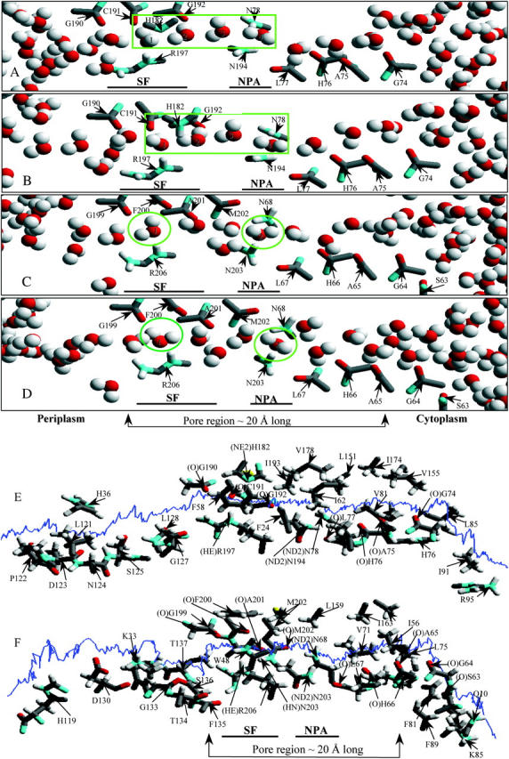
FIGURE 2.

The structure of the H-bonded network of water molecules inside the bAQP1 and GlpF pores. Only the hydrophilic residues lining the pore are illustrated. SF is the selectivity filter region; NPA is the NPA motif. (A and B) The four water molecules, numbered 1 to 4 from left to right, and highlighted by a rectangle, adopt a specific equilibrium orientation in the bAQP1 pore observed in all MC runs. Panel B illustrates the effect of protonation of the NE2 atom of H182. (C and D) Two snapshots from MC simulation revealing the structure of the H-bonded network of water molecules inside GlpF. Two water molecules in the constriction region (SF) and at the NPA motif, highlighted by green circles, adopt specific equilibrium orientations observed in all MC runs. Water pathway along the bAQP1 (E) and GlpF (F) pore. The trajectory of a “tagged” water molecule is represented by the blue curve. Important residues lining the pore (within 4 Å) along the water trajectory are labeled, with individual atoms conventionally colored. For clarity the individual waters are not shown. The figures were generated using our MCICP code.
