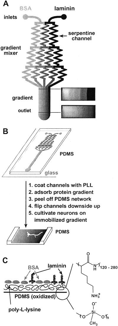
Figure 1.
(A) Schematic drawing of the design of a typical microfluidic network in PDMS that we used for the fabrication of immobilized gradients. Solutions of laminin and BSA were injected into the microfluidic network (inlets). Several streams, each carrying different concentrations of laminin and BSA, were generated in the gradient mixer and combined in a single channel to form a gradient perpendicular to the direction of the flow. The initial step profile created at the junction blurs slightly due to diffusion as the fluid travels downstream. The right-hand side of the diagram shows cross-sectional images of the concentration profile (using pure buffer and fluorescein, D = 5.0 × 10⁻⁶ cm2⋅s−1) of the flow visualized by using a confocal microscope. The shadows in the corners of the confocal images are due to the distortion of the light at the channel walls. (B) The diagram summarizes the steps from the fabrication of the substrate-bound gradient to the cultivation of neurons on the gradient immobilized on the substrate. A gradient was deposited on the floor of the channels by adsorption from the flowing stream. The network of microfluidic channels was removed, inverted, and placed in a culture dish. Neurons were plated on the floor of the channel in the region where the gradient had formed. (C) An idealized schematic diagram of the cross section of the surface composition of a substrate-bound gradient composed of laminin and BSA on PLL.

