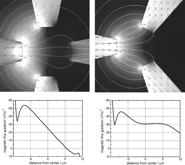
FIGURE 6.
Spatial distribution of the magnetic flux density obtained by numerical simulations for (upper left) a four-pole geometry and (upper right) a three-pole geometry. In both cases, the incoming flux is from the left pole. (Lower left) Magnetic flux density gradients along a horizontal line through the center of the tweezers in case of the four-pole structure and (lower right) as (lower left) but for the three-pole structure.

