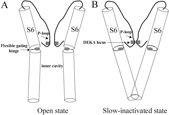
FIGURE 8.
Cartoon of P-loop and S6 configurations within the open state (A) and slow-inactivated state (B) of Na+ channels. Regions with shaded squares and ovals represent the selectivity filter (i.e., the DEKA locus) and the gating hinge (G or S residue), respectively. The gating hinge and/or nearby S6 residues may interact with amino acids at the adjacent P-loop. The DEKA locus and the S6 C-terminus are possible constriction sites for slow inactivation. The front and back P-loops and S6s are removed for clarity. Notice that the inner cavity is smaller in the slow-inactivated state when the S6s are in straight configurations. Sequences of P-loops and S6s are listed in Fig. 1. The intracellular fast-inactivation gate (not shown) occludes the permeation pathway, possibly via the inner cavity.

