
Fig. 2.
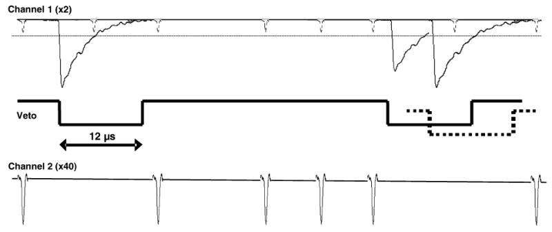
Diagram of the circuit concept used to distinguish between SPE and γ-ray events. Channel 1 has low amplification gain and contains both optical SPE and γ-ray events. A trigger is set just above the SPE level (~10–12 mV, dotted line in channel 1) and is used to suppress (veto) events in channel 2, containing the SPE signal. The dashed line in the middle signal trace indicates a γ-ray event that has randomly occurred before the end of a veto pulse. It extends the veto pulse by retriggering the 12 μs delay.