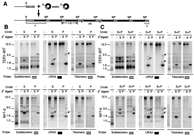
FIG. 3.
Transformation with two species of circle produces arrays derived from only one species. (A) Diagram of telomere structures before and after introduction of a mixture of two species of 1.6-kb URA3-telomere circles that differ only by a single restriction site. Gray and black boxes are blocks of telomeric repeats and URA3, respectively. White boxes are subtelomeric sequence present on DNA circles, and stippled boxes are subtelomeric sequence not present on the circles. Abbreviations: R, S, and P, sites for EcoRI, SalI, and PvuI, respectively; S/P, sites that will either be SalI or PvuI depending upon which circle the site is derived from; J and T, junction fragment with subtelomeric sequences and terminal telomeric fragment, respectively. (B) Southern blots of representative clones of TER1 (top) and ter1-Δ (bottom) transformed with either circle S or circle P are shown hybridized with subtelomere, URA3, or telomeric probe, as indicated. Untransformed control is shown digested with EcoRI, and transformants are shown digested with EcoRI (-), EcoRI-SalI (S), or EcoRI-PvuI (P). The type of transforming circle used is indicated on top. A faint band at 3.2 kb in URA3-probed lanes containing the dark 1.6-kb fragment are trace partials left over from cleaving the tandem arrays. Positions of molecular weight markers (in kilobase pairs) are indicated. (C) Southern blots of two representative clones each of TER1 (top) and ter1-Δ (bottom) transformed with both circle S and circle P are shown hybridized with subtelomere, URA3, or telomeric probe, as indicated. The two clones represent one example each of clones exhibiting tandem arrays of either an S version or a P version. Digests were done as for panel B. (B and C) Junction fragments (J) are marked with arrows in the URA3.

