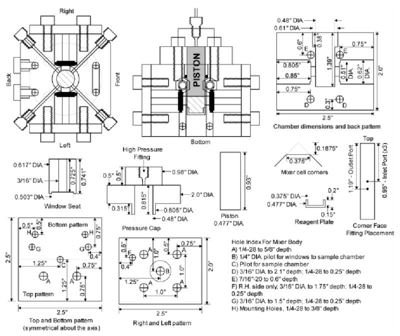
Figure 2.

Two views of the mixing chamber are drawn to illustrate how the pieces fit in context. The left and right, and top and bottom walls of the mixer are combined into single diagrams. The left and right are identical except for hole F. The text section details the drill sizes and depths for the holes (A–H) indexed on the diagram. The top and bottom patterns are symmetrical about the horizontal axis indicated by a faint line. Holes that are not marked with specific dimensions are identical to holes of the same index letter. Additional parts detailed in the paper are also shown with corresponding dimensions.
