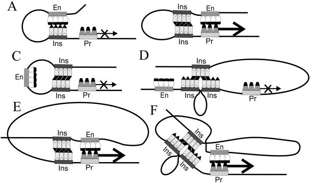
FIG. 4.
Schematic cases of possible interplay among the elements in the regulation of gene expression, as related to the literature data and models and the results of this work. En, Pr, and Ins mark the nucleoprotein complexes of the enhancer, promoter, and insulator, respectively; the thick arrows denote promoter stimulation by the enhancer with ensuing transcription, and the thin, crossed arrows denote lack of stimulation (blocked enhancer-promoter communication). (A) “Basic” arrangement, in which a single intervening insulator fully blocks enhancer-promoter communication. There is ample experimental support, but enhancer trapping as implied in the common “promoter decoy” model has not been demonstrated, and only transient association is consistent with the definition of insulator function. (B) Another basic case, in which pairing of two intervening insulators allows free enhancer-promoter communication, commonly known as insulator mutual neutralization, cancellation, and bypass. There is ample experimental support for this case. (C) Pairing of two insulators around the enhancer locks it in a loop and topologically isolates it from the promoter, commonly known as the loop domain model (corresponds to Fig. 2F). (D) Reverse case, where interaction between a tandem pair and a third downstream insulator topologically isolates the gene promoter from the enhancer (Fig. 3E and F). The actual positioning of the three copies here and in the case shown in panel F is unknown. (E) Pairing of broadly spaced insulators around the enhancer gives the latter enough freedom to approach the promoter region beyond the loop (Fig. 2B). Note the spatial similarity to the “linear” case shown in panel B. (F) Analogous case for an intervening tandem and a third upstream insulator (Fig. 3A). For more detailed comments and references, see the text.

