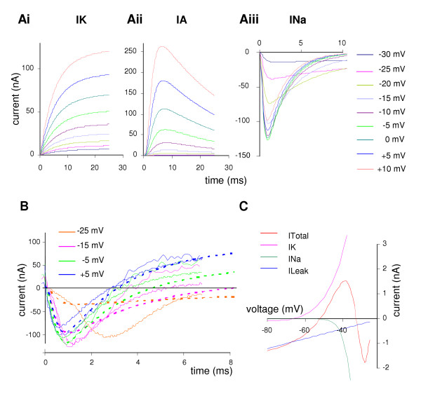
Figure 8.

Simulation of ionic currents under voltage clamp in the B1 motoneuron. A. Transient currents from a holding voltage of -80 mV, showing a series of steps starting at -30 mV and increasing in 5 mV increments. Ai. Sustained outward current, the sum of two (increasing) components; compare the B1 data from Fig. 2A. Aii. Transient outward current, rapidly activating and then decaying; compare to data from Fig. 2C. Aiii. Inward current, showing more rapid activation and inactivation as the steps increase; compare to B1 data in Fig. 6. B. Total current in simulation (bold dotted line) from -50 mV to -25 mV, -15 mV, -5 mV and +5 mV, compared with current recordings from 2 different preparations (thin solid lines). At -25 mV the real data show the effects of an action potential propagated from the contralateral cell, starting about 1.5 ms into the recording (so only one preparation is shown at this step). The bold line in black shows the zero current level. C. Simulated Current – Voltage plot, showing the steady-state outward current (IK) the inward current (INa) the leak current (ILeak) and total current (ITotal). The steady state value of the transient outward current is too small to show on this scale. The steady state total current crosses the x-axis at -52 mV with a positive slope, giving this as the calculated stable resting potential.
