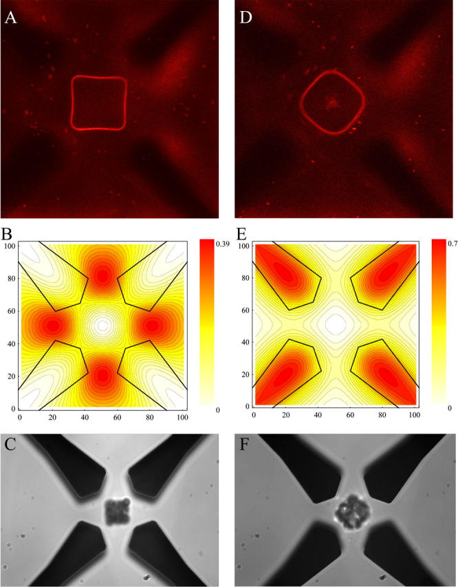
FIGURE 2.

Trapping and electrorotation of GUVs and particles in the dielectric microfield cage. (A) Confocal image of the equatorial plane of a single trapped GUV, labeled with diI-C20:0. (B) Corresponding electrode outline and dielectric field potential in the central horizontal plane in units of the applied mean-square electric field. The difference between two contour lines corresponds to 2%. The dielectrophoretic response of latex particles is shown in C. The second column (D–F) shows images for rotating mode. The electrode voltage and frequency assignments were 4.4 Vrms and 0.75 MHz, respectively. The distance between opposing electrodes is 40 μm.
