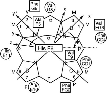
FIGURE 1.
Structure of the heme with the reference coordinate system x′, y′, z′ (R, θ′, Ω′) and magnetic coordinates system, x, y, z (R, θ, φ), shown. The x′, y′ plane is given by the mean plane of the heme in the crystal structure, with the x′ axis passing through the pyrrole B nitrogen, and the z′ axis normal to the heme and oriented to the proximal side. The positions relative to the heme of the residues whose proton dipolar shifts were used to generate the magnetic axes are also shown (proximal residues as rectangles, distal residues as circles). The angle α and κ = α + γ are defined; not shown is the angle β, which measures the tilt of the major magnetic axis, z, from the heme normal, z′.

