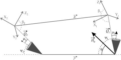
FIGURE 1.
Diagram defining parameters for the tether-in-a-cone model. The axes X, Y, and Z are the axes of the two nitroxides with X along the N-O bond and Z perpendicular to the plane of the nitroxide and with all subscripts referring to nitroxide 1 or nitroxide 2. The two cones are separated by  at their bases and their relative orientation is determined by the angles ψ1, ζ2, and ψ2 (ζ2 not shown). The orientation of the two cones with respect to the magnetic field,
  is determined by the angles θ and φ (φ not shown). The orientations of the tethers,
  and
and  within their respective cones are determined by the angles ν, μ, and λ (ν and λ not shown). The orientation of the tethers with respect to the nitroxide axis systems are determined by the angles α, β, and γ (α and γ not shown). Those angles that are not shown for the sake of simplicity correspond to Euler angle rotations about the appropriate Z axis as defined in Eqs. 2–8.

