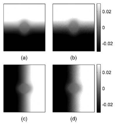
Fig. 8.

Ideal (a) and estimated (b) axial displacement images and ideal (c) and estimated (d) lateral displacement images for the inclusion phantom simulations. Images were obtained by simulating signals for 91 angular insonifications (−45° to 45° ). The depth and width of these images are 4 and 3.5 cm, respectively. The axial direction or the z direction is from top to bottom and the lateral direction or the x direction is from left to right.
