
Figure 1.
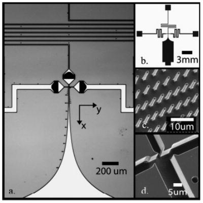
Images of silicon microfluidic mixer. (a) CCD image of mixing region showing three inlet channels with integrated filters (center and side channels), nozzle region at intersection, and exponential mixer exit region (south channel). Dots along the mixing channel are distance markers. (b) Schematic (mask) of the entire microfluidic chip. The inlet (center and side) and exit channels were sized (length and width) to reduce instabilities of focused stream from pressure controller fluctuations. (c) SEM image of filter posts in inlet channels upstream of nozzle region. The filters consist of rows of 1–2-μm spaced posts to avoid clogging. (d) SEM images of nozzles and initial mixing region. Nozzle widths are ~1–3 μm wide and channels are 10 μm deep.