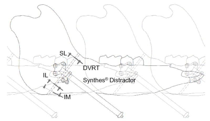
Figure 1.

Schematic drawing of the pig right mandible showing the osteotomy (broken lines) fixed by a Synthes® appliance in an anterior exit configuration and DVRT (Group 2) placement at three different locations. The osteotomy site is drawn as a relatively wide gap only for clarity. SL, superior-lateral; IL, inferior-lateral; IM, inferior-medial. For Group 1 pigs, sonometric crystal pairs instead of DVRTs were placed at the former two locations.
