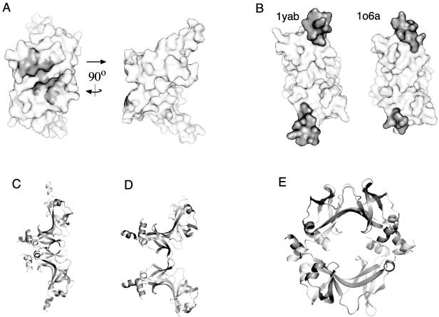
FIG. 2.
(A) Crystal structure of FliN (PDB accession no. 1yab), with the hydrophobic patch indicated by gray coloring. (B) Differing positions of helix 1 (colored gray) in the two FliN crystal structures. In the 1o6a structure, the two helices of the dimer have different apparent lengths because the structural model begins at residue 68 of one subunit and residue 74 of the other. (C) Model for the FliN tetramer based upon the subunit organization seen in the crystal structure of HrcQBC (12). (D) Example of a dimer-dimer contact occurring in the FliN crystal structure 1o6a. (E) Ring-shaped tetramer of FliN subunits seen in the crystal structure 1yab. Panels A and B were prepared using Pymol, and panels C and D were prepared using Rasmol.

