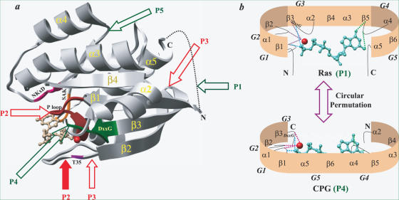
Figure 1.
The figure shows all possible circular permutations for GTPases, using the structure of the prototype Ras and compares overall architecture in Ras and cpGTPase. (a) The structure of Ras is shown as gray ribbons (PDB code, 5P21). GTP is shown as ball and stick model while Mg2+ is shown as sphere (red). The regions harbouring sequence motifs G1–G5 are depicted in different colours along the structure. G1 (10Gx4GKS/T17) is shown in brown, G2 (T35) in blue, G3 (57DxxG60) in green, G4 (116NKxD119) in violet and G5 (145SAK/L147) is colored orange. The arrows indicate ways to create new N- and C-termini. Green arrows represent an allowed permutation that satisfies the features required for binding and hydrolysis. They are P1 (G1–G2–G3–G4–G5), P4 (G4–G5–G1–G2–G3) and P5 (G5–G1–G2–G3–G4). Permutations P2 (G2–G3–G4–G5–G1) and P3 (G3–G4–G5–G1–G2) represented by red arrows do not seem to be viable (see text). Open and filled arrows of P2 indicate two different ways of creating the same permutation P2. (b) A cartoon representation of the permutations P1 and P4 observed in classical Ras like GTPases and cpGTPases to indicate that the structural features essential for GTP binding and hydrolysis are preserved in both. GTP and Mg2+ are shown as in (a). The hydrogen bond to guanine base is depicted in green, phosphate in cyan and Mg2+ in magenta, respectively. The locations of the sequence motifs G1–G4 are indicated.

