
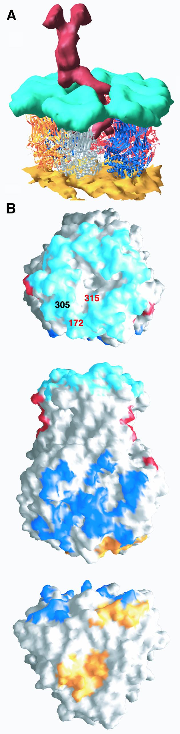
Fig. 7. Contacts with the outer layer of the viral particle. (A) View of a type II channel cut out of the cryo-EM reconstruction of the complete viral particle. The atomic model, shown as ribbons color coded as defined in Figure 5A for the different ITs, replaces the density corresponding to VP6. The EM density of the VP2 layer is shown in gold and the density of the VP7 layer in cyan. The viral hemagglutinin VP4 is shown in red. (B) Surface representation of VP6, trimer P, highlighting the regions in contact with the other layers of the viral particle. Regions contacting rotavirus VP7, VP4 and VP2 are colored cyan, red and gold, respectively. The surface in contact with neighboring trimer P′ is colored blue. Top: contacts with VP7. The amino acids involved in defining the subgroup epitopes (I and II, see text) of group A rotavirus are labeled (in different colors to indicate that they belong to different subunits). This view also shows a depression at the center, on the 3-fold axis. Residues lining the walls of this depression do not make contacts with VP7. Middle: side view of trimer P (red in Figure 5A). This is the only trimer to contact two VP4 molecules in adjacent type II channels. Regions seen in contact with trimer P′ are indicated in blue. Bottom: regions of contact between trimer P and VP2. The latter contacts do not follow the local 3-fold symmetry of the VP6 trimer.