
Figure 2.
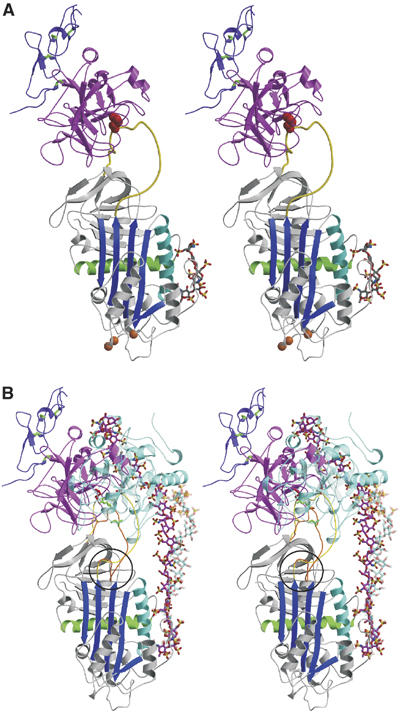
Crystal structure of the Michaelis complex between pentasaccharide-activated AT and fXa. (A) Stereo view of the complex with AT colored as before, the protease domain of fXa in magenta, and the second EGF-like domain of fXa in purple (with disulfide bonds shown in green). The orientation of fXa on AT is slightly to the left of the long axis of AT, and is rotated significantly to the left to engage in direct exosite contacts with the top surface of AT. The positions of the AT mutations which allowed crystal contacts to form are indicated by orange balls. (B) It is clear from the stereo representation of the AT–thrombin Michaelis complex superimposed on the AT–fXa complex why one is insensitive to hinge region expulsion and the other critically depends on hinge region extension (hinge region is circled). The RCL of the thrombin complex is orange, with green rods for P4 Ile390 and P1 Arg393, and the RCL from the fXa complex is yellow, with P4 and P1 residues colored red. Thrombin (semitransparent cyan) is oriented towards the front of AT and the RCL enters the active site of thrombin by the most direct line, with P4–P1 aligned along the z-axis (into the plane). In contrast, fXa is translated towards the left and rotated so that the P4–P1 enters the active site cleft along the x-axis (from right to left). The position and orientation of the active site cleft of fXa is dictated by the exosite contacts, which are evident to the left of the RCL. The forward position and orientation of thrombin permit short heparin chains (∼16mer) to bridge the heparin-binding sites of the two molecules (semitransparent cyan rods from the structure by Li et al, 2004). In contrast, based on the position and orientation of fXa observed here, a 28mer (magenta rods for the modeled heparin chain) would be predicted to be the minimal required heparin length for bridging the AT–fXa Michaelis complex.