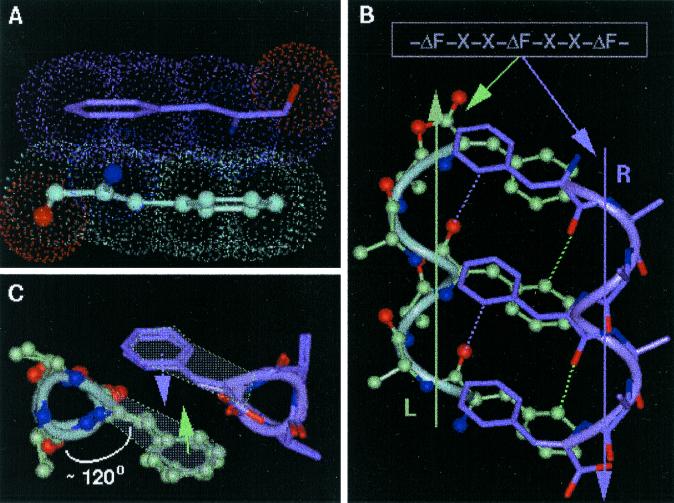
Figure 1.
Design strategy of HH21. (A) The planarity of ΔPhe (ΔF) residue and hence the possible stacking of two ΔPhe side chains belonging to two different secondary structural elements. (B) The model sequence -ΔPhe-X-X-ΔPhe-X-X-ΔPhe- and the speculated right-handed helix (marked R, colored green), a left-handed helix (marked L, colored mauve), Cβ atoms of the residues X are shown for clarity. The planar ΔPhe side chains with restricted rotamer flexibility stack one above the other in each helix, where the vector perpendicular to mean plane of all of the atoms of ΔPhe makes an angle of approximately 45° to the helix axis. The specific groove in helix R, involving the back of the ΔPhe stack acts as a host for the ΔPhe stack from the helix L, wherein the entire ith ΔPhe residue of helix R stacks on to the entire (i ± 3n, n = 0, 1, 2) ΔPhe residue of the helix L, resulting in three sets of extended phenyl embrace arrangement at the helix–helix interface. Dotted lines represent the expected C—H—O hydrogen bonds. (C) View along the helical axes, showing orientation of ΔPhe residues with respect to helical axis and their stacking. Three wedges and grooves along the helical axis can be seen (see Figs. 8 and 9 for more information).

