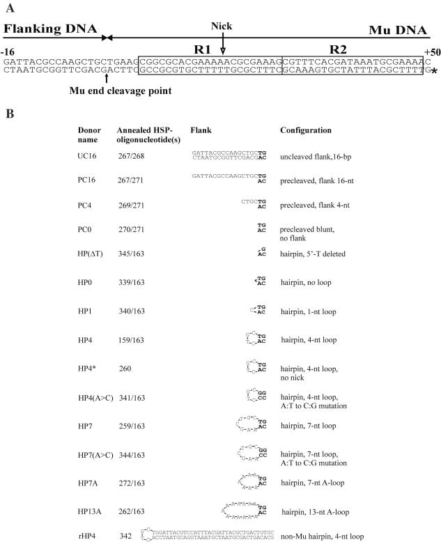
Figure 1.
Donor DNA substrates. (A) Substrate schematic representation. All the Mu-specific substrates contain ∼50 bp, starting from the Mu R-end and including the MuA-binding sites R1 and R2 (22). These substrates also include a flanking DNA region, which can be in duplex DNA, linear single strand or in a hairpin loop configuration. Some substrates contain nucleotide substitutions close to the transposon end or within the loop region [see (B)]. The depicted 16 bp flanking sequence has been shown earlier to support efficient catalysis by MuA in an in vitro model substrate assay (22), and the standard loop sequences are derived from that same sequence by joining the endmost Mu-specific 3′-adenine to various nucleotide positions in the opposite strand of the duplex. The Mu end cleavage point is indicated by a solid arrow and the position of the radioactive label by an asterisk. The open arrow shows the position of the nick present in most substrates [see (B)]. (B) Substrate characteristics. The donor substrates were made by annealing one or two oligonucleotides to form double-stranded species as indicated. Most of the hairpin substrates were generated from two oligonucleotides, and these substrates therefore contain a nick [within the R1 MuA-binding site, see (A)]. This nick does not interfere with in vitro transposition reactions as indicated by a direct comparison of reactions with the nicked and corresponding unnicked substrate (compare lanes 4 and 12 in Figure 5). The endmost nucleotides of the transposon DNA are shown in bold, and flanking nucleotides are indicated in regular font. The rHP4 substrate includes a randomly chosen non-Mu sequence with two conserved base pairs mimicking the transposon end.

