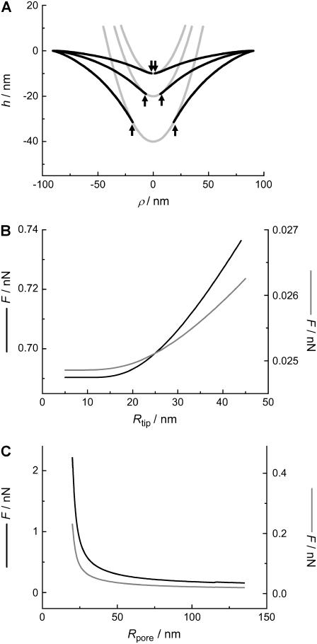
FIGURE 7.
(A) Calculated membrane shape (small gradient approximation) as a function of maximum penetration depth (10 nm, 20 nm, 40 nm), using the parameters Rtip = 20 nm and Rpore = 90 nm, assuming a fluid membrane (σfluid = 1.0 mN m−1, κfluid = 0.1·10−18 J). The arrows indicate the point c of detachment between tip and membrane. (B) Force F to maintain a constant penetration depth h0 = 10 nm as a function of the tip radius Rtip using typical parameters for a membrane in the gel (black line) and fluid phase (gray line); parameters: σgel = 5.0 mN m−1, κgel = 1.0·10−18 J, σfluid = 1.0 mN m−1, κfluid = 0.1·10−18 J, and Rpore = 90 nm. (C) Force F at h0 = 10 nm as a function of the pore radius Rpore for a membrane in the gel (black line) and fluid phase (gray line) using the following parameters: Rtip = 20 nm, σgel = 5.0 mN m−1, κgel = 1.0·10−18 J, κfluid = 0.1·10−18 J, and σfluid = 1.0 mN m−1.

