
Fig. 1.
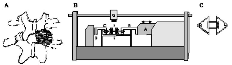
(A) Sketch of two lumbar vertebrae and their left and right facet joints. On the right joint, the posterior aspect of the facet capsule has been drawn. The two dotted lines indicate the locations of the cuts through the laminae of the inferior and superior facet processes of the respective vertebrae to enable producing bone-capsule-bone specimens suitable for testing parallel to the collagen fibers. (B) Side-view drawing of the materials testing apparatus (Tytron 250, MTS, Inc. fitted with a tissue bath. Actuator (A) is fitted with over-the-bath extension arms (B and C) in series with a force transducer (D). The facet capsule (E) is coupled to the extension arms by custom made pin-clamps (F) that attach to the respective trimmed facet processes of the joint. A CCD camera (G) is mounted above the specimen to facilitate optical measurements of strain. (C) Capsules tested perpendicular to the orientation of the collagen fibers were cut free from the facets and mounted acrylic plates glued to both the superficial and deep surfaces. The acrylic mounting plates attached to the locking pin in the pin clamps.