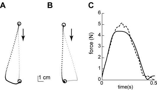
Figure 3.

Simulation of adaptation to a velocity dependent curl field using a spindle-like basis set. (A) Hand paths from the early phase of training. Black dots represent a movement in the force field and grey dots represent a movement in the null field (catch trial). (B) Hand paths from the late phase of training. (C) The dotted line represents the velocity dependent forces applied to the simulation arm in the direction perpendicular to the movement direction as a function of time. The solid line represents the predicted forces by the internal model consisting of spindle-like basis elements.
