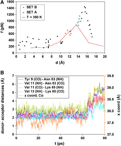
FIGURE 2.
(A) Force extension profile of the I27 domain observed in the simulations. The forces and extensions shown in this figure are average values calculated after the system was allowed to relax after the displacement of the restraint point (see Methods). The solid black, red, and green circles correspond to the results of the “short simulations”. Simulations for the green (set A) and the red (set B) points were further extended to 10 ns. Sets A and B include points that occurred one step (set A) and two steps (set B) before strand separation in the “short simulations”. The results of the “long simulations” are not shown in this figure. The red line and red open circles represent the force versus extension curve for 350 K with a elastic constant of 2 kcal/mol Å2. (B) Time course of the distances between donors and acceptors of the H-bonds between β-strands A′ and G of I27. The x-position of the Leu-89 Cα during the first 80 ps of equilibration is also shown.

