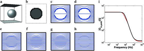
Figure 3.
Spherical cell model (rcell = 10 μm) for nearly insulating and realistic membrane resistivities. (a) Perspective drawing with ideal parallel plane electrodes (top black and bottom gray) that provide an applied electric field, E⃗app. (b) Approximation of spherical cell (black region assigned Me1+m+e2; white and gray regions assigned Me1 and Me2, respectively). (c–h) Equipotentials (blue) for ρm = 108 Ω m and f = 100 Hz, 100 kHz, 1 MHz, 10 MHz, 100 MHz, and 1 GHz, respectively. (i) Magnitude of the frequency-dependent membrane field gain at the cell's poles, Gm,pole(f), predicted here (red) and by a second-order analytic model (black) (29).

