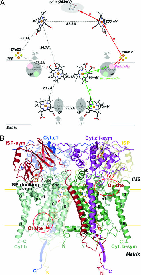
Fig. 1.
Prosthetic groups and subunit structures of the cyt bc1 complex. (A) Arrangement of prosthetic groups in the dimeric bc1 complex and illustration of the electron bifurcation at the Qo site. The bL, bH, and c1 heme groups are shown as ball-and-stick models, and the [2Fe2S] clusters are depicted as cpk models. Carbon atoms, black; nitrogen, blue; oxygen, red; sulfur, yellow; iron, brown. The Qo pockets near the IMS side of the membrane and the Qi pockets near the matrix side are labeled and shaded in gray. Cyt c is shown as a gray shaded oval. Distances between redox centers are given on the left half of the diagram, and the redox potential for each center is given on the right. The high- and low-potential ET paths are depicted with red and green arrows, respectively. Circles in pink and light green within the Qo pockets are hypothesized distal-QH2 and proximal-Q binding sites, respectively. (B) Ribbon diagram of the dimeric cyt b, cyt c1, and ISP subunit in the mitochondrial bc1 complex. Two symmetry-related cyt b subunits are shown (green and light green). The eight TM helices of cyt b are denoted with letters A–H. Helices A–E form one bundle in which the two b-type hemes (bL and bH in ball-and-stick models) reside; helices F–H form the other bundle. The ISP subunit (yellow and red for the symmetry pair) has an extrinsic soluble domain with a [2Fe2S] cluster at its tip, connecting to a TM segment by a flexible neck. The extrinsic domain of cyt c1 (blue and magenta for the symmetry pair) with its heme group is rigidly attached to its TM helix. The locations for the two active sites (Qo and Qi) per monomer in cyt b are labeled. The surface depression in cyt b at the IMS side of the membrane is labeled as the ISP-docking crater.

