Fig. 3.
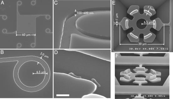
Scanning electron micrographs of the Si track (A–D) and the SiO2 rotor (E and F). (A) Overview of the track. When the M. mobile cells were settled onto the substrate, most attached within the square-shaped central depression (60 × 60 μm) created by Si etching and coated with fetuin molecules. A cell moving around in the square would eventually reach a side wall and begin to move along it until it was introduced into a circular track. (B) Enlarged image of the circular track. A straight track extended from the square area is asymmetrically connected to the circular track. A cell moving from the straight track enters the circular track and circles in a clockwise direction, jumping the gap formed by the straight track, guided by the sharp tip. (C) Tilted view of the circular track. The track was steeply carved by anisotropic etching with reactive ion. The depth of the etching was ≈500–600 nm. (D) Two cells are gliding along the side wall of the track. (Scale bar, 1 μm.) (E) Hexagonal microrotors during the process of fabrication (top view). Rotors are tethered to the Si base by two thin bridges designed to break upon sonication, releasing the rotors. (F) Rotors have protrusions that fit the circular grooves shown in A–C (tilted view). The heights of the protrusions are ≈1.4–1.5 μm.

