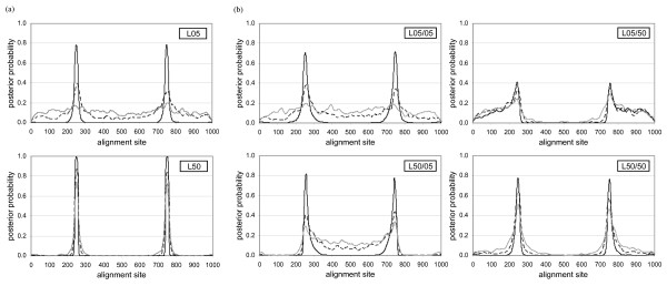
Figure 6.
Identification of (a) reciprocal and (b) non-reciprocal recombination breakpoints in DualBrothers. The Y-axis of each graph represents the posterior probability of a site being proposed as a recombination breakpoint, while the X-axis represents each site on the alignment. In all cases, the simulated recombination breakpoints are at positions 250/251 and 750/751. The different lines on each graph represent the amount of subsequent substitution (λ) simulated (in substitutions per site): black solid line, 0.00; black dashed line, 0.25; and grey solid line, 0.50.

