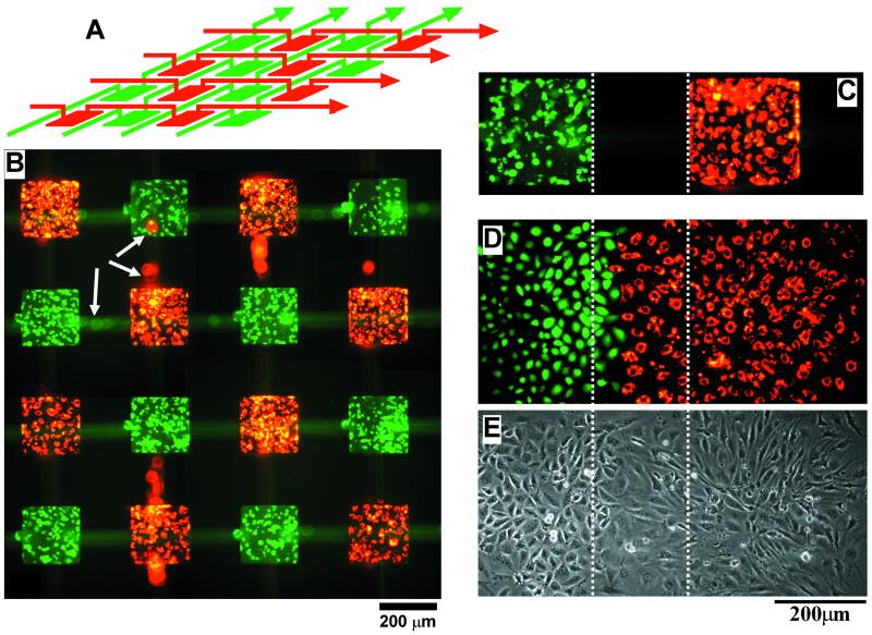
Figure 5.
Fluorescence picture (B) of CMFDA-labeled ECVs (green) and DiI-labeled BCEs (red) deposited in a chessboard-like pattern by using the stamp design in A. To show the overlaying weaving channel structures, the PDMS stamp was not removed before taking the picture in B. The white arrows indicate cells that were inside the channels in the top layer of the PDMS stamp; these cells appear blurred because they were above the focal plane of the microscope. The cells in B were cultured for 42 hr before the fluorescence picture was taken. (C) A picture of a confluent layer of cells before the PDMS stamp was removed; this image is slightly diffuse because the PDMS stamp might have caused optical aberrations. Pictures taken in fluorescence (D) and in phase contrast (E) show the spreading and growth of the two cell types after the removal of the PDMS stamp. The pictures were taken 20 hr after removal of the stamp. The three images in C–E are registered; the dotted lines show the relative orientation of the patterns. The BCEs spread more rapidly than the ECVs by a factor of 2–3.

