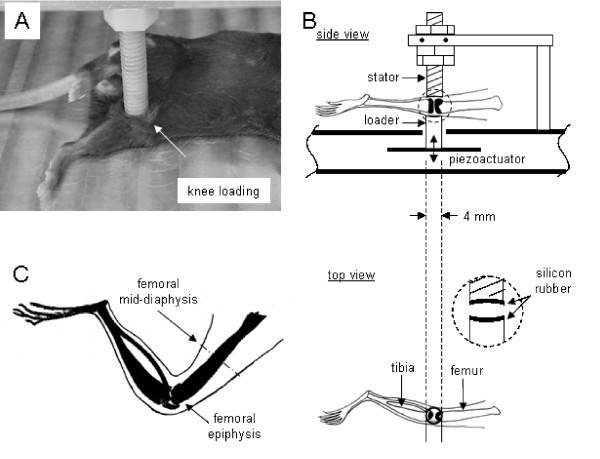
Figure 1.

Setup of a mechanical loader for knee loading used in this study. (A) Custom-made piezoelectric mechanical loader for knee loading. (B) Schematic diagram illustrating the loading site. The knee is placed between the stator and the loader (4 mm in diameter). (C) Hindlimb showing the femoral mid-diaphysis (site for a bone histomorphometric analysis).
