
Figure 3.
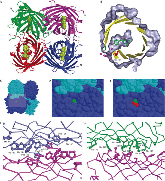
TurboGFP crystal structure. (A) The overall structure of TurboGFP. Cα traces are in green, violet, red and blue. The chromophore is shown as green van der Waals spheres. (B–E) A pore leading to the TurboGFP chromophore. The chromophore is highlighted in green and Val 197 in red. (B) Protein surface (grey) is cut away to show the pore and the chromophore cavity. Sections of secondary structure elements are shown as yellow cartoons. Relevant water molecules are depicted as magenta spheres. (C–E) The pore remains unobstructed on tetramerization. (F,G) Contacts between TurboGFP monomers. Two TurboGFP monomers are shown as Cα traces, with contact residues shown as balls and sticks of the same colour as the particular monomer. For clarity, only one set of residues is labelled. (F) The more extensive contact area having mainly hydrophobic character is shown. (G) The less extensive contact area, composed of a mixture of polar and hydrophobic interactions is shown.